H.O. Alternator replacement and big 3 wiring
#1
 05-25-2010, 12:27 AM


Join Date: Dec 2009
Location: Quad Cities, IL
Posts: 3,279
I was having voltage problems with my stock 105A alternator. So I spent a week researching, emailing, etc. to determine what would be the best value for me. I know that my sound system current draw is below 100A (based on calculations, gain settings, and fusing). I also know that I need more than 105A to properly maintain 14V with the system on, A/C on, while driving.
I researched alternators from Ohio Generator, Irragi, McGowan, Buesings (local shop), and a few other online sellers of high output alternators. My research told me that Ohio Gen has the best (at $525), followed by Irragi (at $400 and $320). My local shop can do whatever the case will allow for under $200. McGowan had a $140 amp alt that has an upgraded 140A stator, regulator, and rectifier for $150 with a 2-year warranty and no core. I decided that the McGowan alt would let me evaluate an incremental increase in output while letting me still get my factory alt respun at the local shop. While I’ll have the cost of one Irragi alt invested, I’ll have two working alternators that are sufficient for my needs.
On to the installation:
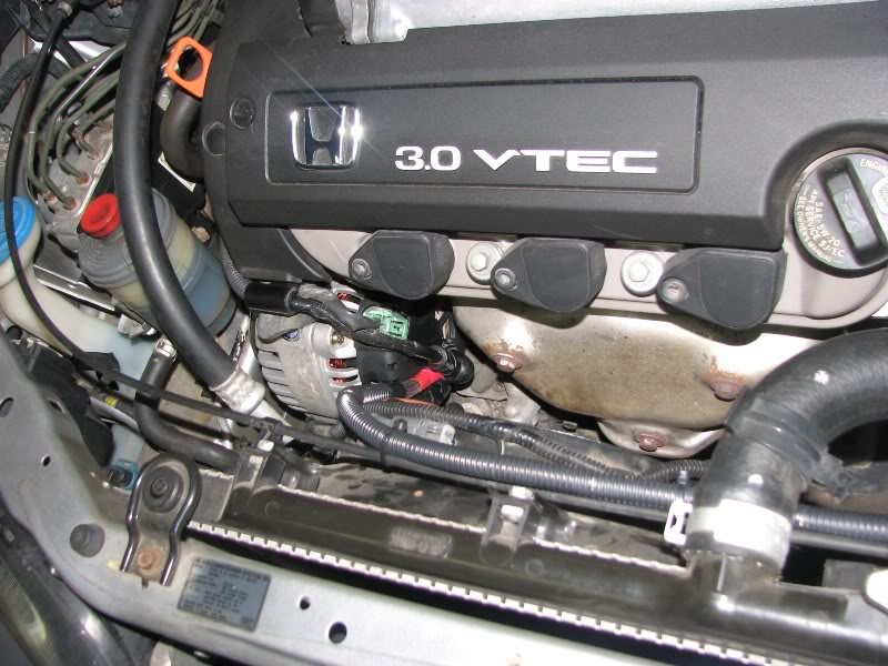
The factory alt is located on the front passenger corner of the J30A1 V6. To remove the alt you need to do the following:
1. Remove front bumper and lower plastic protector skirt (clips and 10mm)
2. Remove passenger cooling fan (10mm socket)
3. Remove passenger engine trim panels (flat head)
4. Disconnect alt wiring (10mm)
5. Remove serpentine belt (14mm wrench on tensoner)
6. Remove alternator bolts (one 12mm (3/8” socket) and one 14mm (1/4” socket/wrench). There is limited space for the lower 14mm bolt due to the belt tensioner.
7. The manual says to “maneuver” the alternator out of the engine bay. They could have just said “good luck”. It took me 30 minutes to get it out. Oddly enough, once the orientation was determined, the new one went into place easily – in 15 seconds. The trick is to orient the mounting locations facing up, go in pulley first between the A/C piping and block/manifold. I also removed the exhaust manifold shield to gain an extra 1/2".
front bumper comes off so easily
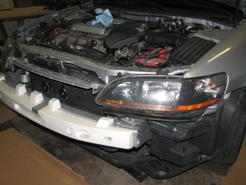
radiator fan out
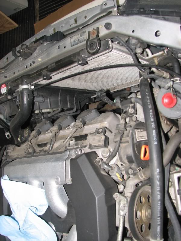
old coming out
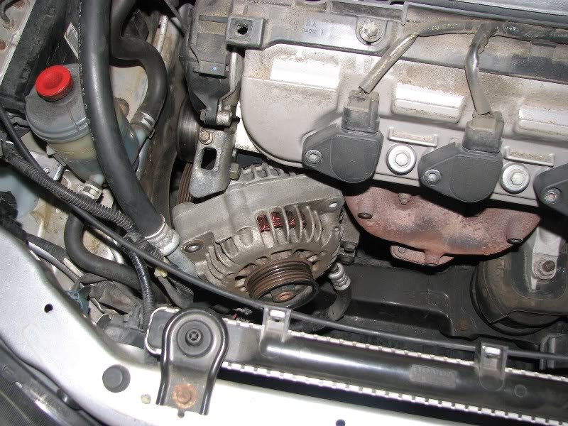
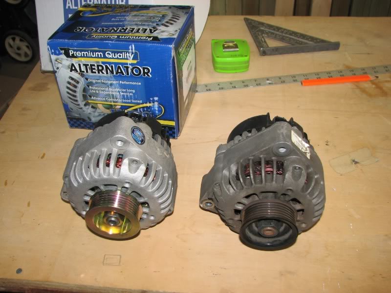
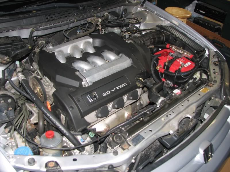
new vs old (clean vs dirty)
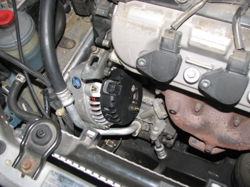
new alt going in
I researched alternators from Ohio Generator, Irragi, McGowan, Buesings (local shop), and a few other online sellers of high output alternators. My research told me that Ohio Gen has the best (at $525), followed by Irragi (at $400 and $320). My local shop can do whatever the case will allow for under $200. McGowan had a $140 amp alt that has an upgraded 140A stator, regulator, and rectifier for $150 with a 2-year warranty and no core. I decided that the McGowan alt would let me evaluate an incremental increase in output while letting me still get my factory alt respun at the local shop. While I’ll have the cost of one Irragi alt invested, I’ll have two working alternators that are sufficient for my needs.
On to the installation:
The factory alt is located on the front passenger corner of the J30A1 V6. To remove the alt you need to do the following:
1. Remove front bumper and lower plastic protector skirt (clips and 10mm)
2. Remove passenger cooling fan (10mm socket)
3. Remove passenger engine trim panels (flat head)
4. Disconnect alt wiring (10mm)
5. Remove serpentine belt (14mm wrench on tensoner)
6. Remove alternator bolts (one 12mm (3/8” socket) and one 14mm (1/4” socket/wrench). There is limited space for the lower 14mm bolt due to the belt tensioner.
7. The manual says to “maneuver” the alternator out of the engine bay. They could have just said “good luck”. It took me 30 minutes to get it out. Oddly enough, once the orientation was determined, the new one went into place easily – in 15 seconds. The trick is to orient the mounting locations facing up, go in pulley first between the A/C piping and block/manifold. I also removed the exhaust manifold shield to gain an extra 1/2".
front bumper comes off so easily
radiator fan out
old coming out
new vs old (clean vs dirty)
new alt going in
Last edited by keep_hope_alive; 06-01-2010 at 09:51 PM.
#2
05-25-2010, 12:30 AM
Join Date: Dec 2009
Location: Quad Cities, IL
Posts: 3,279
Big 3 Grounding
Replacing the alternator is only half the job. When you add a high power sound system, you need to upgrade all of the associated alternator wiring, engine grounding, and battery grounding – which we call “the big 3”. Battery ground is common and easy – run a new ground wire from battery negative terminal to chassis (not a shock tower or body part). My factory ground was decent – 4awg to chassis, 10awg to body. I added a second 4awg wire to chassis. Dual 4 awg is good for 250A. By chassis – I mean the frame rail under the battery tray. I find removing the intake hosing and battery tray to be a common approach to improved grounding. Engine to Chassis is next, and very easy on my Accord and Camry. The transmission housing is accessible under the intake hosing, and has an 8awg jumper from the factory. Since this wire is the return path for my alternator – it needs to be rated for the alternator amperage (based on 1ft length). I have a short 4awg jumper with new terminals.

Replacing the alternator is only half the job. When you add a high power sound system, you need to upgrade all of the associated alternator wiring, engine grounding, and battery grounding – which we call “the big 3”. Battery ground is common and easy – run a new ground wire from battery negative terminal to chassis (not a shock tower or body part). My factory ground was decent – 4awg to chassis, 10awg to body. I added a second 4awg wire to chassis. Dual 4 awg is good for 250A. By chassis – I mean the frame rail under the battery tray. I find removing the intake hosing and battery tray to be a common approach to improved grounding. Engine to Chassis is next, and very easy on my Accord and Camry. The transmission housing is accessible under the intake hosing, and has an 8awg jumper from the factory. Since this wire is the return path for my alternator – it needs to be rated for the alternator amperage (based on 1ft length). I have a short 4awg jumper with new terminals.
Last edited by keep_hope_alive; 06-01-2010 at 09:51 PM.
#3
05-25-2010, 12:37 AM
Join Date: Dec 2009
Location: Quad Cities, IL
Posts: 3,279
The most overlooked, and incorrectly applied part of the big 3 is the alt to battery positive. Your alternator terminals are very important, and the alternator is supposed to be responsible for powering your entire vehicle – sound system + the whole car. The alternator is sized for the vehicle, not the sound system. If you can’t maintain >13.5V with your sound system on and the engine at 1000RPM – you need to turn it down or get a larger alternator. But first, you can upgrade the wiring to reduce overall voltage drop – and it may solve your problem.
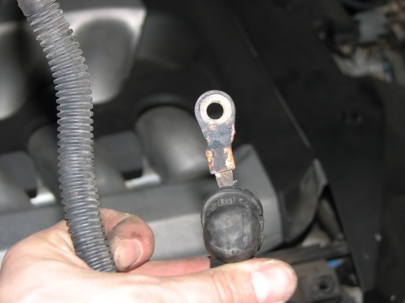
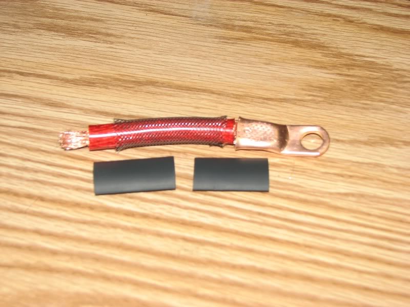
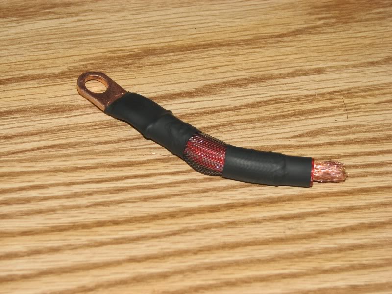
I noticed the factory 6awg alt wire had an awfully corroded terminal. I replaced this with a new 4-6awg ring terminal with a 1/4" opening. You want 1/4" terminals for the alt. This new termination should get maximum current though the factory wire and has heat shrink and the factory loom. The other end is a funky right angle terminal that you can’t buy in stores. I’ll be upgrading the factory wire to 4awg once I get a new terminal for it (I’m not cutting the fuse box housing).
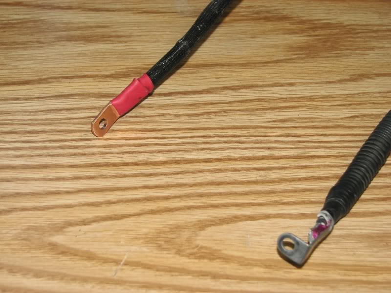
factory fuse box end with new alt terminal end
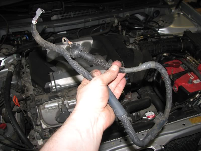
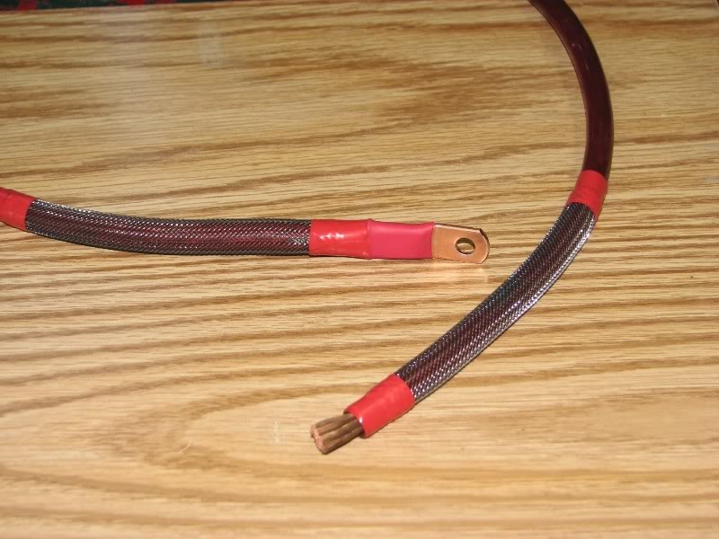
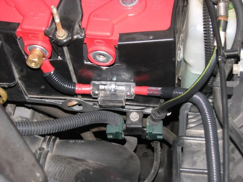
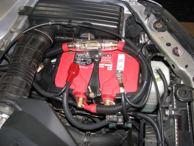
Since the factory wire wasn’t sufficient, I added a second wire from the alt terminal to the battery positive. I used good 4awg wire, with a 1/4” terminal, heat shrink, tech flex, and high-temp split loom. On the other end I have a MAXI 100A fuse holder mounted to the battery shield (bolted). This holder has a very short jumper to the positive terminal with a 3/8” ring terminal, tech flex, heat shrink, loom, and tape – a stout little guy. The rest of the wire has high temp split loom and zip ties securing it to factory cabling (stationary).
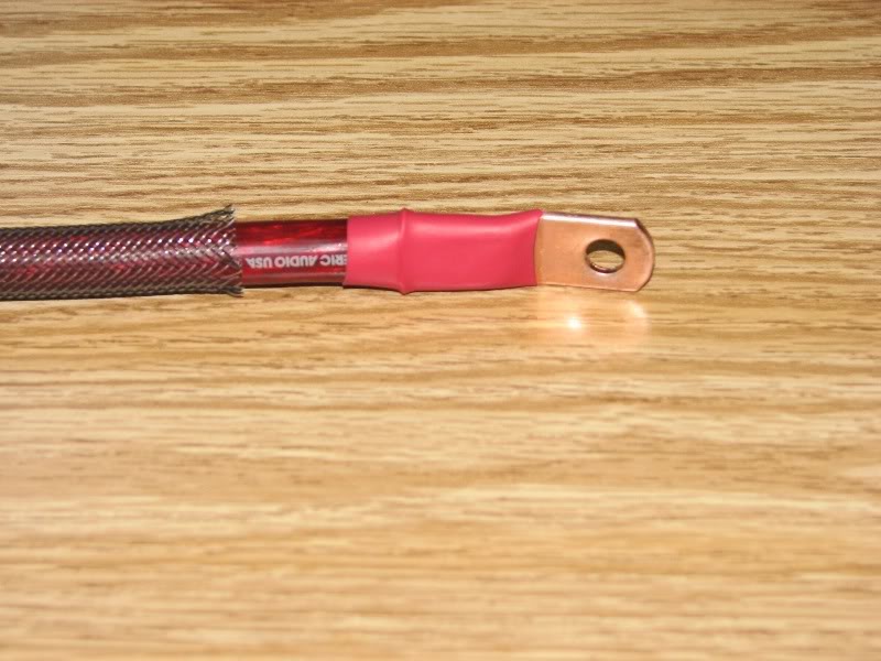
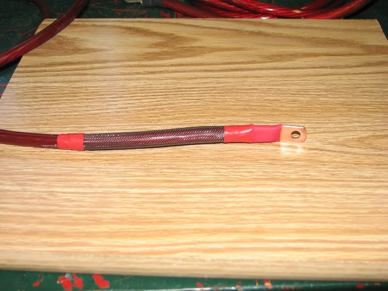
battery positive to new fuse holder
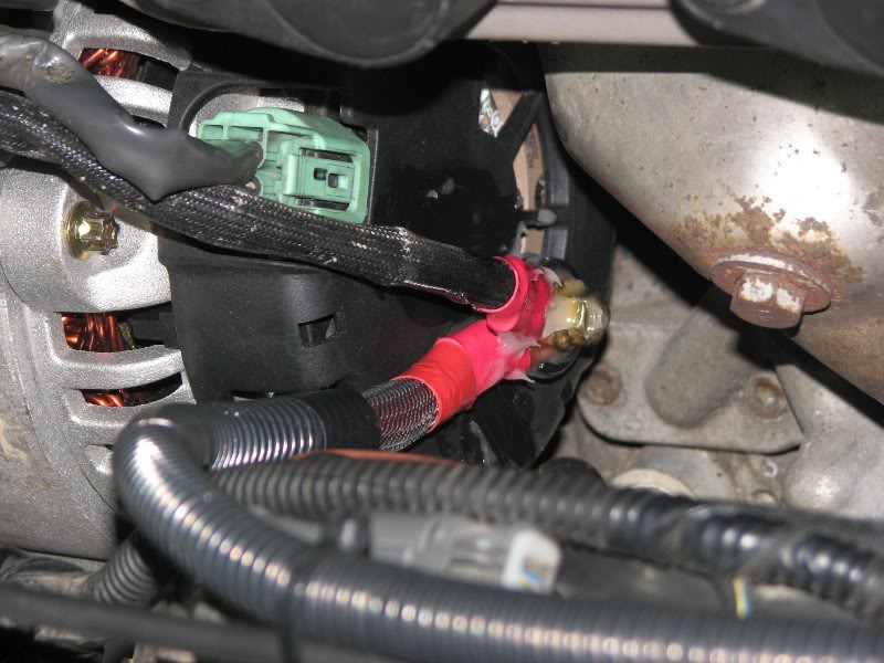
alt terminal with protectant.
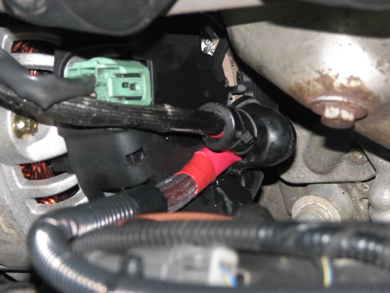
I got the boot back on and zip tied it into place.
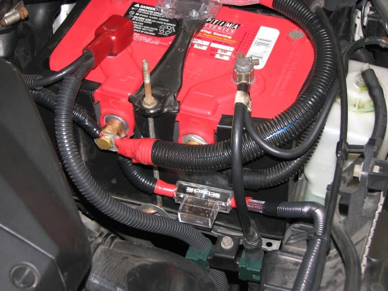
The finish result, all terminals cleaned and coated with protectant.
I noticed the factory 6awg alt wire had an awfully corroded terminal. I replaced this with a new 4-6awg ring terminal with a 1/4" opening. You want 1/4" terminals for the alt. This new termination should get maximum current though the factory wire and has heat shrink and the factory loom. The other end is a funky right angle terminal that you can’t buy in stores. I’ll be upgrading the factory wire to 4awg once I get a new terminal for it (I’m not cutting the fuse box housing).
factory fuse box end with new alt terminal end
Since the factory wire wasn’t sufficient, I added a second wire from the alt terminal to the battery positive. I used good 4awg wire, with a 1/4” terminal, heat shrink, tech flex, and high-temp split loom. On the other end I have a MAXI 100A fuse holder mounted to the battery shield (bolted). This holder has a very short jumper to the positive terminal with a 3/8” ring terminal, tech flex, heat shrink, loom, and tape – a stout little guy. The rest of the wire has high temp split loom and zip ties securing it to factory cabling (stationary).
battery positive to new fuse holder
alt terminal with protectant.
I got the boot back on and zip tied it into place.
The finish result, all terminals cleaned and coated with protectant.
Last edited by keep_hope_alive; 06-01-2010 at 09:51 PM.
#4
05-25-2010, 12:47 AM
Join Date: Dec 2009
Location: Quad Cities, IL
Posts: 3,279
When everything is said and done, there are always things you'd like to do over. The new alt wire is routed safely and securely, but It could be a bit longer and out of the way a bit more. As it is, quickly pulling the MAXI fuse lets you disconnect it from the alt if needed.
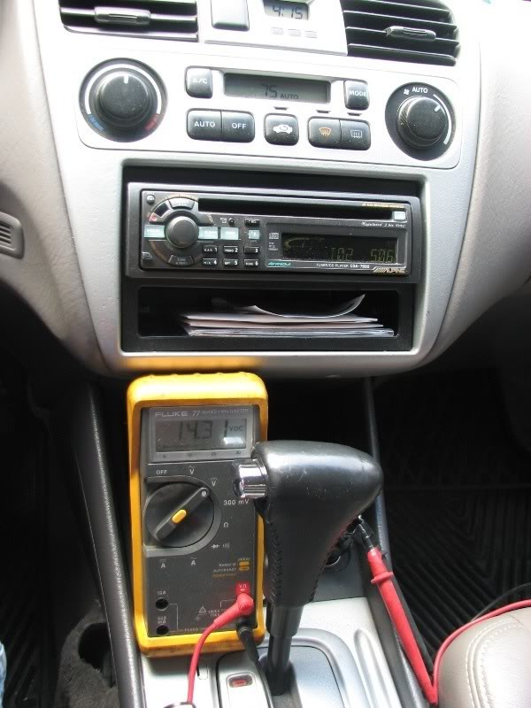
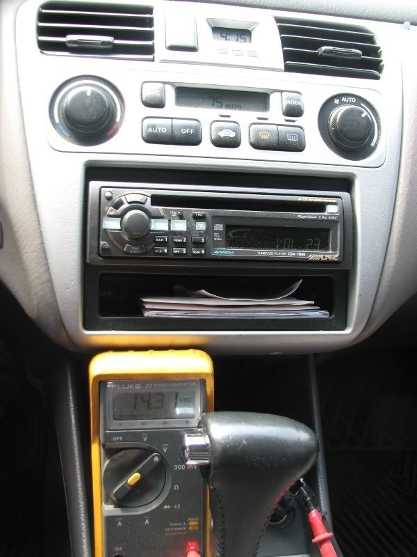
The end result? I took some DMM readings from the cigarette lighter output (which is off a 10AWG lead direct to the battery and powers the head unit).
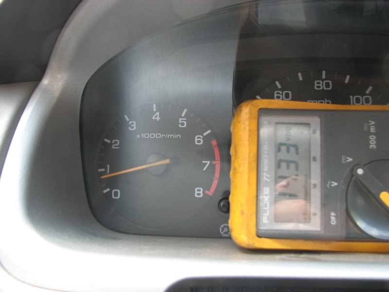
At Idle (600RPM) with the stereo at a normal, high listening volume, and it was 90 degrees that day so 75 is full A/C:
I'm happy, but a new battery is in my near future. The Redtop has 6-7 years on it and it's age is showing. A Diehard Platinum AGM Group 34 is planned next.
The end result? I took some DMM readings from the cigarette lighter output (which is off a 10AWG lead direct to the battery and powers the head unit).
At Idle (600RPM) with the stereo at a normal, high listening volume, and it was 90 degrees that day so 75 is full A/C:
I'm happy, but a new battery is in my near future. The Redtop has 6-7 years on it and it's age is showing. A Diehard Platinum AGM Group 34 is planned next.
Last edited by keep_hope_alive; 06-01-2010 at 09:52 PM.
#5
05-25-2010, 09:15 PM
Join Date: Dec 2009
Location: Quad Cities, IL
Posts: 3,279
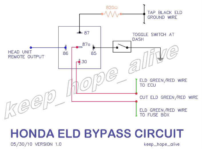
A new challenge is the ELD (electrical load detector).
The ELD is going to be an issue for all of us. I have a few ideas how to get this thing functioning properly. We can't bypass it, and we want it functioning as it's a good idea for fuel economy and battery life. What we need to do is include the audio system current draw.
I think my solution will utilize a high current shunt resistor to monitor audio system current draw (similar to what the ELD does now with the ignition system current draw), and then use a circuit to combine the two signals and send one new signal to the ECU that mimics the original signal but takes the audio system into account. I'd like to keep the total cost down below $40 so anyone can do it (half that cost will be the shunt itself). I envision a transistor or two, a comparator, maybe a few op amps, possibly a 555 timer, etc. - basic inexpensive components. I hope to avoid a microcontroller.
This has become a #1 priority for me, so a solution will be found. Lucky, I develop custom electronic circuits for a hobby/career. Of course, i'll share my results with everyone.
#6
05-26-2010, 02:09 AM
Unregistered
Posts: n/a
I see you live in IL! You should give me a hand! haha
But in all seriousness, a great DIY and a wealth of great info! Looks very professional and obviously well worth it! I have a volt gauge that is hardwired into my cig lighter and the voltage varies all the time. At stop lights w/ my system I run to 12v volts but if I turn on the turn signal the motor will rev a bit and it will go back to 14v.
But in all seriousness, a great DIY and a wealth of great info! Looks very professional and obviously well worth it! I have a volt gauge that is hardwired into my cig lighter and the voltage varies all the time. At stop lights w/ my system I run to 12v volts but if I turn on the turn signal the motor will rev a bit and it will go back to 14v.
#7
05-26-2010, 07:54 AM
Join Date: Dec 2009
Location: Quad Cities, IL
Posts: 3,279
I see you live in IL! You should give me a hand! haha
But in all seriousness, a great DIY and a wealth of great info! Looks very professional and obviously well worth it! I have a volt gauge that is hardwired into my cig lighter and the voltage varies all the time. At stop lights w/ my system I run to 12v volts but if I turn on the turn signal the motor will rev a bit and it will go back to 14v.
But in all seriousness, a great DIY and a wealth of great info! Looks very professional and obviously well worth it! I have a volt gauge that is hardwired into my cig lighter and the voltage varies all the time. At stop lights w/ my system I run to 12v volts but if I turn on the turn signal the motor will rev a bit and it will go back to 14v.
#8
05-27-2010, 12:28 AM
Join Date: Dec 2009
Location: Quad Cities, IL
Posts: 3,279
A good Tech Tips article on the Honda ELD and how it functions (from 1998).
http://www.diymobileaudio.com/forum/...ing-system.pdf
I found this very useful in aiding me in my quest to "correct" the ELD issue.
Essentially, I want the ELD system to function correctly, and to include the sound system load profile (which requires a delay in reducing output due to music being a dynamic load). But I do want it to operate normally when the sound system demands are low or off.
The real trick is going to be protecting the ECU from any damage when that 5V signal is intercepted.