
H22A Accord Swap
#21
 02-10-2015, 07:48 PM


I have to look more at the photos and may need to know the wiring colors on some of them too.
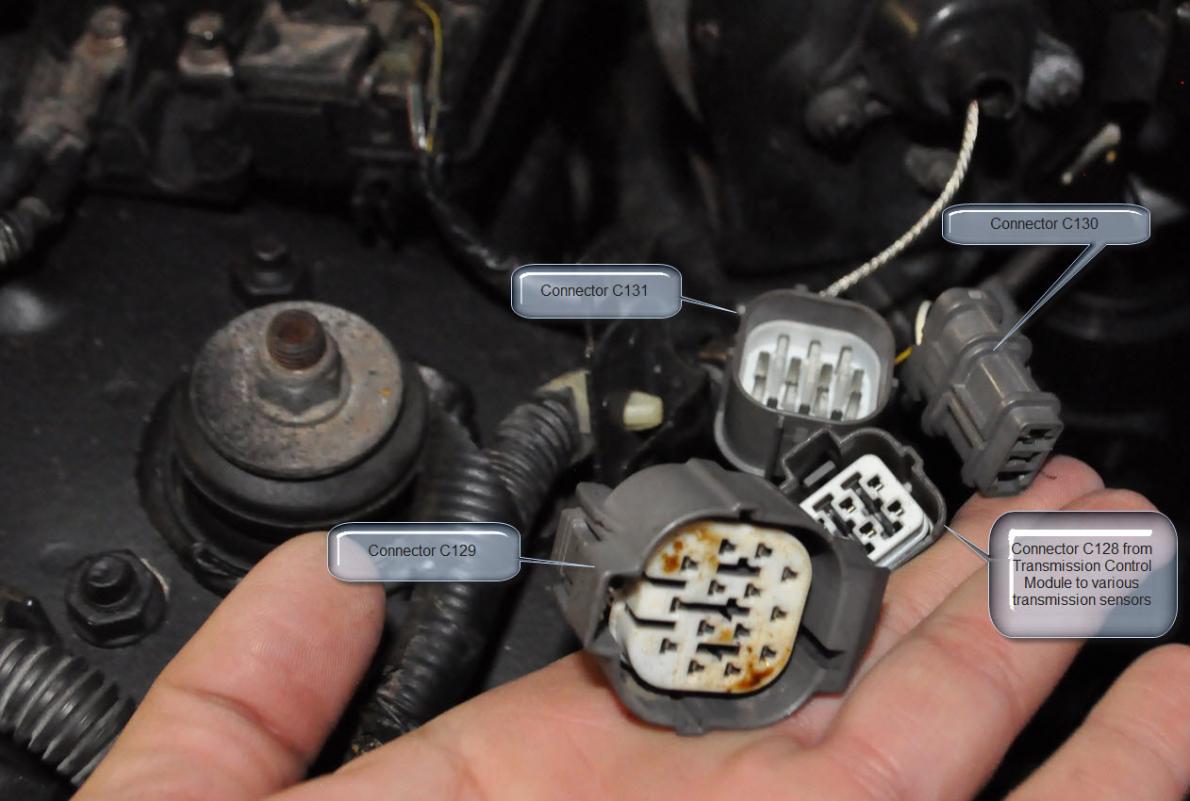
For now, the 4 connectors on the right branch engine harness looks to be Connectors C128, C129, C130, and C131. C128 is for Accords with A/T.
Connector C129 and C131 looks to be similar to the H22A blue connectors. The wiring pin-out may or may not be all the same though.
There are a bunch of guides out there; but, here are two that may help if you haven't seen them yet:
A Guide on How to do an H22A Swap for Accord - Honda Forum : Honda and Acura Car Forums
5th Gen H22A Swap
#23
02-12-2015, 11:28 AM
Looking at the circuit diagrams, these look to be the 1994- 1995 Accord wire pin-outs. Honda's circuit diagrams for the 5th generation Accords did not summarize each connector like later circuit diagrams. I may or may not have missed the unlisted ones.
The wire terminal numbering depends on whether it is a male or female connector. (See attached image for explanation.)
This post will be for the right rear engine compartment connectors: C129, C130, and C131.
94-95 Accord (OBD-I)
Harness Connector C129 (14-Gray) (Right rear engine compartment):
1 Wht/Yel___MAP sensor input to ECM
2 Yel/Wht___ECM reference voltage to MAP sensor
3 Grn/Wht__ ECM sensor ground to MAP sensor
4
5 Orn/Blk___ ECM HO2 Sensor control
6 Wht/Red__ Heated Oxygen Sensor input to ECM
7 Yel/Blk____Voltage to HO2 Sensor with ignition in ON or START (runs through Main Relay)
8 Grn/Yel___ ECM VTEC valve control (EX)
9 Wht/Blk___ EGR valve lift sensor input to ECM
10
11 Blu/Blk___VTEC Pressure Switch input to ECM (EX)
12 Blk______ Ground (G101) to ECM
13 Red/Yel__ IAT sensor input to ECM
14 Brn/Blk__ Ground (G101) to Data Link Connector and shielding for various sensors
Harness Connector C130 (Right rear engine compartment):
1 Blk/Wht__ Ign voltage to Starter; A/T (via neutral safety switch); M/T via Starter Cut Relay
2 Blk/Yel___ Ign switch voltage to Ignition Coil (DX, LX); Ign switch voltage to distributor (EX)
Harness Connector C131 (14-Gray) (Right rear engine compartment):
1 Yel/Grn__ ECT sending unit to temperature gauge
2 Brn/Blk__ Ground (G101) to ECM
3 YelBlu___ ECM reference voltage to EGR valve lift sensor
4 Blk______Ground (G101) to ECM
5 Orn_____ ECM input to CYP sensor (distributor)
6 Orn/Blu___ECM input to TDC sensor (distributor)
7 Blu/Grn__ ECM input to CKP sensor (distributor)
8 Red/Wht_ ECT sensor input to ECM
9 Wht____ ECM sensor ground to CYP sensor (distributor)
10 Wht/Blu_ECM sensor ground to TDC sensor (distributor)
11 Blu/Yel_ ECM sensor ground to CKP sensor (distributor)
12 Grn/Blk_Lock-up Control Solenoid Valve B (A/T)
13 Yel____ Lock-up Control Solenoid Valve A (A/T)
14 Wht/Grn_ ECT (Fan) Switch B input to Radiator Control Module
#24
02-12-2015, 11:36 AM
This post will be for the left rear engine compartment connectors: C133 and C134. You should still verify your own wiring.
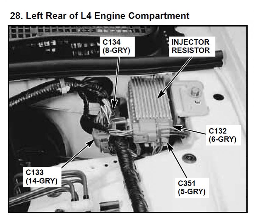
Connector C133 (14-Gray) (Left rear engine compartment):
1 Yel/Blk_____Voltage to IAC valve w/ ign in ON or START (run through Main Relay); terminal no. 1 or 2
2 Yel/Blk____ Voltage to IAC valve w/ ign in ON or START (run through Main Relay); terminal no. 1 or 2
3 Blk/Blu____ ECM IAC valve control
4 Brn_______ ECM Fuel injector control (Injector #1)
5 Red_______ ECM Fuel injector control (Injector #2)
6 Blu_______ ECM Fuel injector control (Injector #3)
7 Yel_______ ECM Fuel injector control (Injector #4)
8 Blk/Yel____ Ignition switch (IG) signal input to alternator
9 Wht/Red___ ECM alternator FR signal
10 Wht/Blu___ Alternator warning lamp (L) signal to gauge assembly
11 Wht/Grn___ Alternator (C) output signal
12 Orn________ VSS output to ECM, Cruise Control, Gauge, & Transmission Control Module (A/T)
13
14 Grn/Blu____ ECM sensor ground for various sensors
Connector C134 (8-Gray) (Left rear engine compartment):
1 Wht/Yel____ ECM Fuel Injection Air (FIA) Control (EX)
2 Grn________ ECT (Fan) Switch A input to Radiator Fan Control Module
3 YelBlu______ ECM reference voltage to TP sensor
4 Blk/Yel_____ Ignition voltage to Fuel Injection Air (FIA) Control Solenoid Valve (EX)
5
6 Blu________ ICM Engine Speed Output (RPM) to tach
7 Yel/Grn____ ECM ignition output signal to Ignition Control Module (ICM)
8 Red/Blk____ ECM TP sensor input
#25
02-12-2015, 11:41 AM
Based on what was posted in this link:
5th Gen H22A Swap
I added additional info to theirs as follows. When lengthen the wiring, you do not have to do it at the listed connector, just along the wire circuit. Use your own judgment with where to lengthen the wiring. -- This is just for informational purpose. Verify wiring, take precautions and do at your own risk.
Sensor wires to lengthen:
Connector C129 (14-Gray) (Right rear engine compartment):
Connector C131 (14-Gray( (Right rear engine compartment):
Connector C133 (14-Gray) (Left rear engine compartment):
Connector C133 (14-Gray) (Left rear engine compartment):
Connector C134 (8-Gray) (Left rear engine compartment):
Connector C131 (14-Gray) (Right rear engine compartment):
NOTE: There is no ECT switch B on the JDM H22, just spare back the connector. (Connector C131, terminal 14 � Wht/Grn wire is for the ECT (Fan) Switch B)
Wires to add:
5th Gen H22A Swap
I added additional info to theirs as follows. When lengthen the wiring, you do not have to do it at the listed connector, just along the wire circuit. Use your own judgment with where to lengthen the wiring. -- This is just for informational purpose. Verify wiring, take precautions and do at your own risk.
Sensor wires to lengthen:
Connector C129 (14-Gray) (Right rear engine compartment):
Connector C131 (14-Gray( (Right rear engine compartment):
Connector C133 (14-Gray) (Left rear engine compartment):
- IAT (GRN/BLU and RED/YEL wires): Too short, needs to reach driver side of intake manifold. (Connector C129, terminal no. 13 has the Red/Yel wire) (Connector C133, terminal no. 14 has the Grn/Blu wire)
- MAP (YEL/WHT, GRN/WHT, and WHT/YEL wires): Too short, needs to reach wherever on the firewall you mount the MAP sensor. (Connector C129, terminal no. 1 has the Wht/Yel wire; terminal no. 2 has the Yel/Wht wire; and terminal no. 3 has the Grn/Wht wire)
- EGR Lift solenoid (GRN/BLU, WHT/BLK, & YEL/BLU): Too short, needs to reach passengers side of intake manifold. (Connector C129, terminal no. 9 has the Wht/Blk wire) (Connector C131, terminal no. 3 has the Yel/Blu wire) (Connector C133, terminal no. 14 has the Grn/Blu wire)
- H02s (GRN/BLU, WHT/RED, ORN/BLK, & YEL/BLK): Too short, needs to be run to O2 sensor, near oil filter. (Connector C129, terminal no. 5 has the Orn/Blk wire, terminal no. 6 has the Wht/Red wire; and terminal no. 7 has the Yel/Blk wire) (Connector C133, terminal no. 14 has the Grn/Blu wire)
Connector C133 (14-Gray) (Left rear engine compartment):
- IAC valve (BLK/BLU and YEL/BLK): Too short, needs to reach top of intake runners, in the middle. (Connector C133, terminal no. 1 or 2 has the Yel/Blk wire; and terminal no. 3 has the Blk/Blu wire)
Connector C134 (8-Gray) (Left rear engine compartment):
- ECT switch A: This will need to be extended to the thermostat housing on the passenger side of the back of the head. The ECT sensor and ECT sending unit fit fine (under the distributor.) (Connector C134, terminal no. 2 has the Grn wire)
Connector C131 (14-Gray) (Right rear engine compartment):
NOTE: There is no ECT switch B on the JDM H22, just spare back the connector. (Connector C131, terminal 14 � Wht/Grn wire is for the ECT (Fan) Switch B)
Wires to add:
- VTEC Solenoid: Grn/Yel on Prelude harness > Pin A4 on ECU // SENSOR LOCATION: Near distributor
- VTEC Pressure Switch: Lt Blu on Prelude harness > Pin D6 on ECU // SENSOR LOCATION: Near distributor
- Blk/Red > Ground
- IAB: Pink on Prelude harness > Pin A17 on ECU // SENSOR LOCATION: Drivers side of intake manifold
- Blk/Yel > 12V
- Knock Sensor: Red/Blu on Prelude harness > Pin D3 on ECU // SENSOR LOCATION: Middle back of block
#26
02-24-2015, 02:19 PM

Holy Cow! Thats Alot To Take In! Im Gonna Have To Study That Hard And Write Alot Of It Down, I Swapped The Wiring Harness From The F22B1 Accord Engine Onto The H22 And Aside From Changing The Injector Plus Everything Else Plugged Up, Had To Change The Coolant Water Neck To Add For Another Temp Sensor And The Distributer Wouldnt Plug Up, Whoever Did The Swap Into The 97 Prelude I Have Put An OBD2 Distributer In It So I Ordered One For A 92-96 OBD1 H22A1 Cause It Looked Exactly Like The Plugs On My Accord Harness "I Hope" Im Not Sure Why I Would Need To Add A V-Tec Solenoid Wire Cause My Accord Harness Has One, The Others Im Gonna Have To Run All This Down, Thanks So Much For Taking The Time To Help Me Out! I Really Appreciate It!

Thread
Thread Starter
Forum
Replies
Last Post
twoaudio
Engine & Internal
1
08-03-2008 01:38 PM
jdm_gadget
PRIVATE For Sale / Trade Classifieds
4
07-16-2008 10:18 PM