
2014 Accord Head Unit Replacement and Function


Thread Starter
|
Super Moderator
Joined: Dec 2009
Posts: 3,279
From: Quad Cities, IL
Investigation into the frequency response of the factory radio has shown disappointing equalization and filtering.

this is the electrical signal taken directly into a SoundDevices USBpre soundcard and viewed on TrueRTA.
measured sound pressure level at the headrest
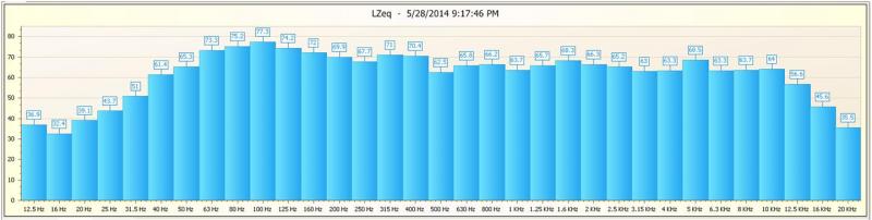
measured sound pressure level 6 inches in front of front door speaker (door open)

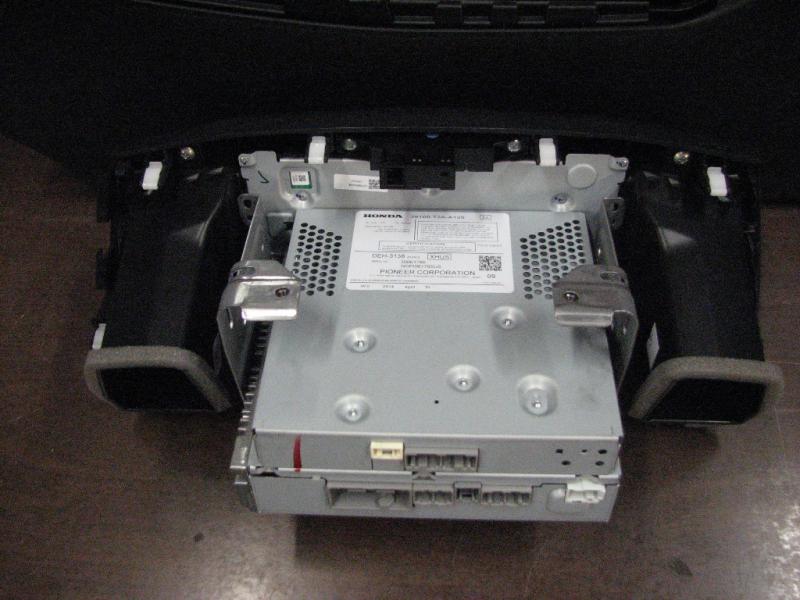
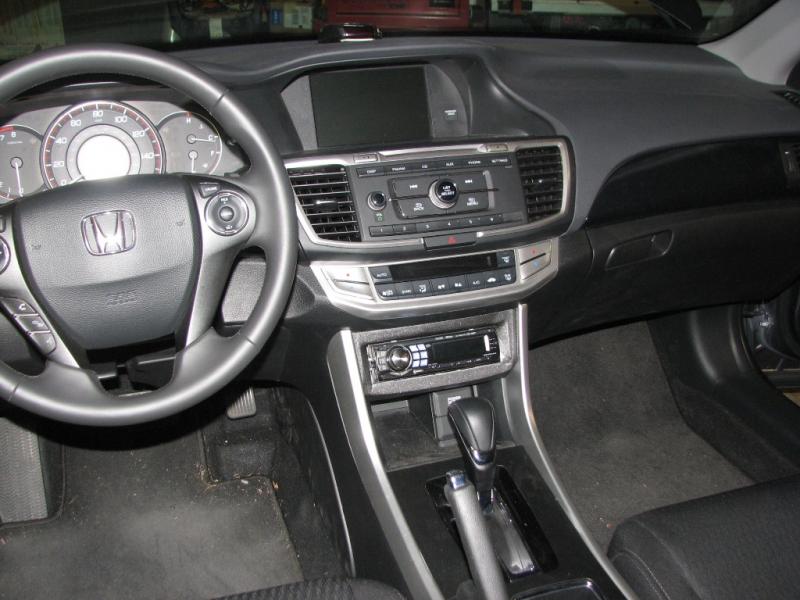
Removing the factory radio requires removal of the lower pocket (two screws) after removing the silver trim pieces.
Two screws are located below, visible using a mirror and 8mm socket/driver


Top cover pries off (use a thin nylon tool starting in the front right corner)
Two screws on the top

once loose, pull straight out. it is clipped into the lower AC unit housing, and other parts of the dash. the left side is behind a piece that includes the tube for air return/temp sensor.

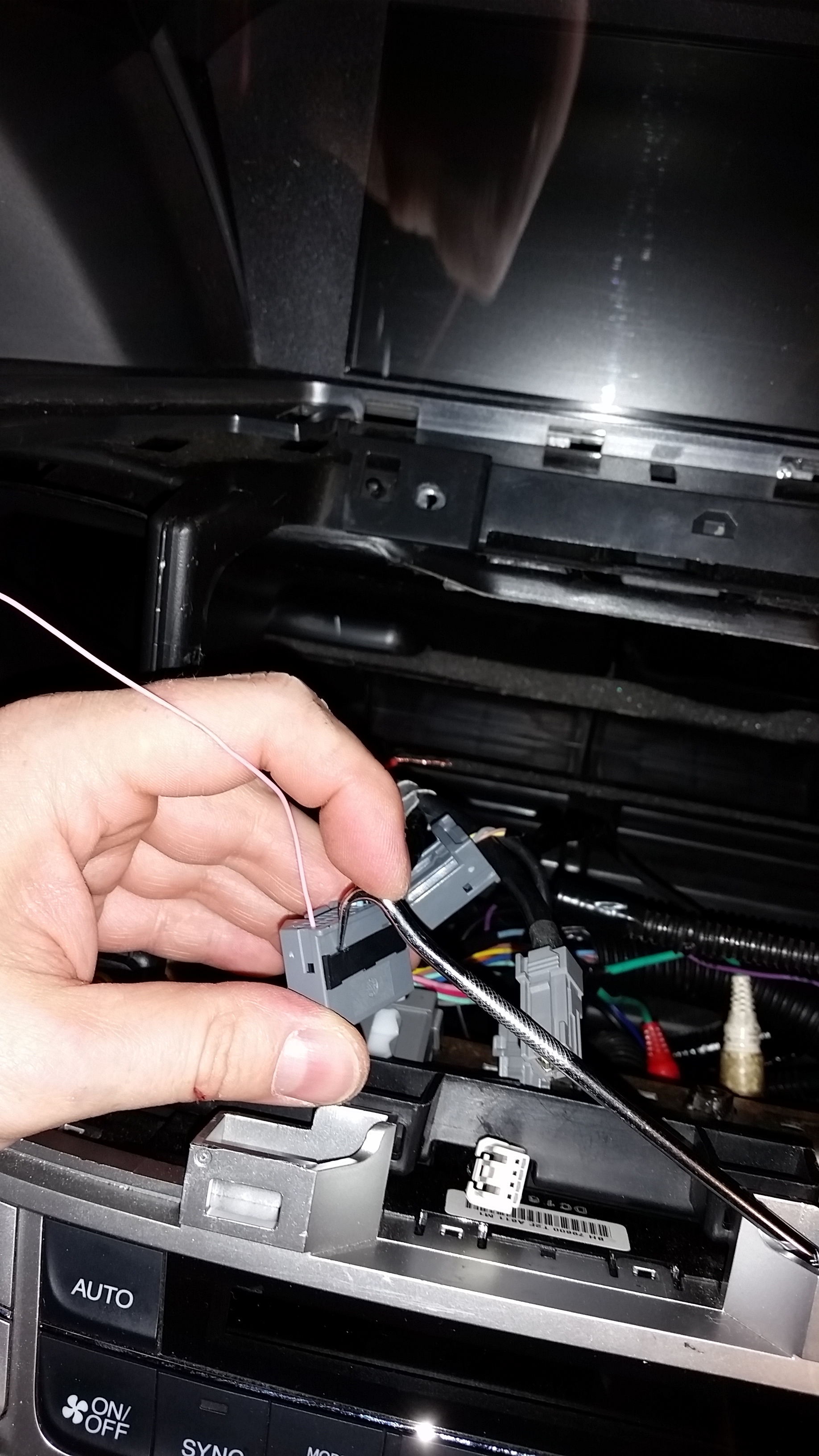
the radio will come out 1" or so. then rotate up and disconnect the hazard wire harness. you will then keep rotating up and see the rest of the harnesses

disconnect all harnesses. the main harness has a small white tab in a white clip that rotates. push down on the tab to release the clip, and rotate the clip to loosen the harness (same kind on driver's door window control). you can remove the A/C unit as well to have more space

this is the electrical signal taken directly into a SoundDevices USBpre soundcard and viewed on TrueRTA.
measured sound pressure level at the headrest
measured sound pressure level 6 inches in front of front door speaker (door open)
Removing the factory radio requires removal of the lower pocket (two screws) after removing the silver trim pieces.
Two screws are located below, visible using a mirror and 8mm socket/driver
Top cover pries off (use a thin nylon tool starting in the front right corner)
Two screws on the top
once loose, pull straight out. it is clipped into the lower AC unit housing, and other parts of the dash. the left side is behind a piece that includes the tube for air return/temp sensor.
the radio will come out 1" or so. then rotate up and disconnect the hazard wire harness. you will then keep rotating up and see the rest of the harnesses
disconnect all harnesses. the main harness has a small white tab in a white clip that rotates. push down on the tab to release the clip, and rotate the clip to loosen the harness (same kind on driver's door window control). you can remove the A/C unit as well to have more space
Thread Starter
|
Super Moderator
Joined: Dec 2009
Posts: 3,279
From: Quad Cities, IL
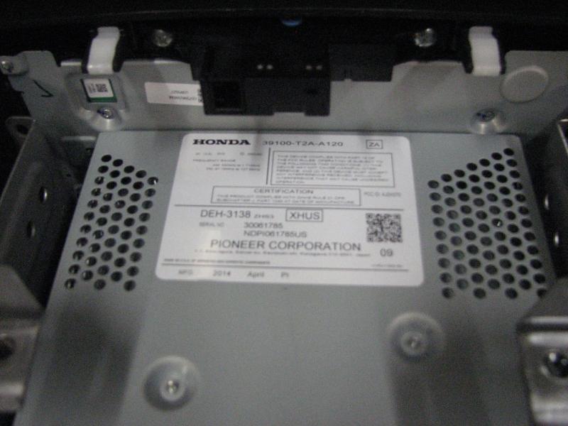
factory radio
A schematic of the radio wiring:
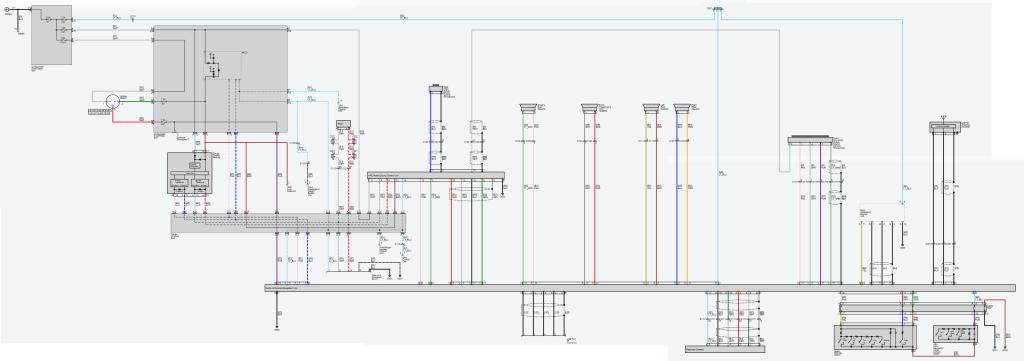
for the full image click this link, then click the lower right magnifying glass twice
2014 Accord Audio System.jpg Photo by phat_funky_beats | Photobucket
A schematic of the radio wiring:
for the full image click this link, then click the lower right magnifying glass twice
2014 Accord Audio System.jpg Photo by phat_funky_beats | Photobucket
Thread Starter
|
Super Moderator
Joined: Dec 2009
Posts: 3,279
From: Quad Cities, IL
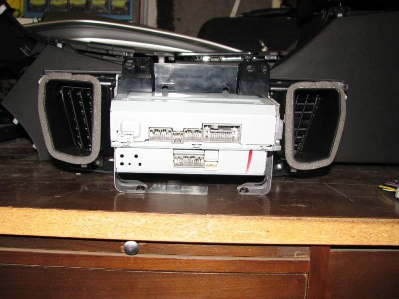
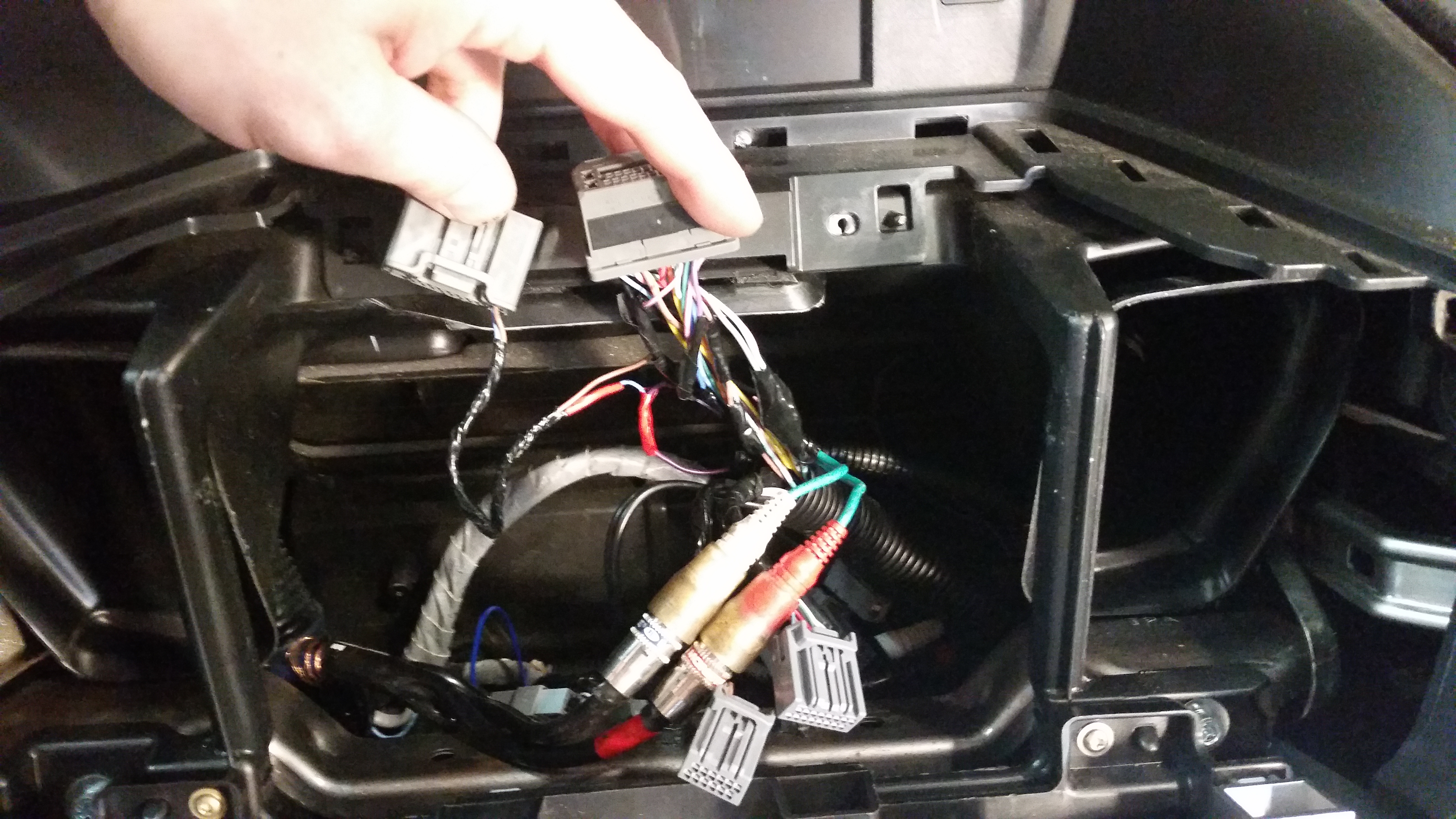
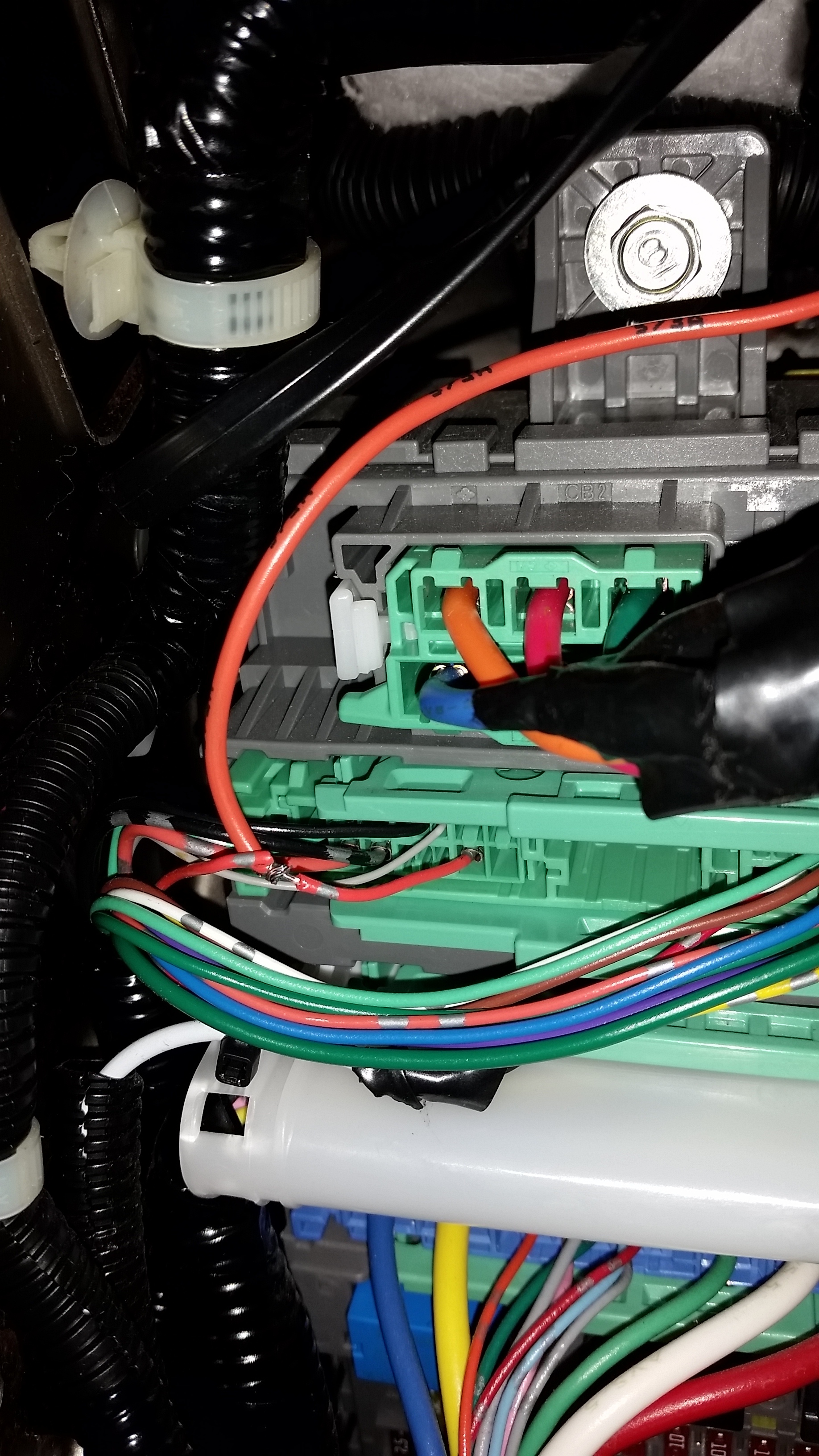
Looking at the schematic and harness we can see what the clips do.
Main clip
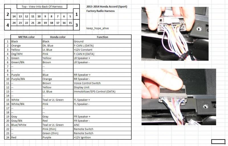
The aftermarket harness adapters are missing 5 wires and use the orange and orange/white for CANbus - not illumination/dimming.
Another harness is for the ANC/BT controller(s). 2013 and 2014 have slight differences here in the number of external units.
Another harness is for the rearview camera.
A few harnesses are for the iMid screen in the upper dash.
There is a USB harness for the lower dash USB socket.
And an Antenna harness for an external antenna amplifier - power, signal, ground.
If you review the schematic above you can see what each harness and each wire does.
There are currently aftermarket dash kits that physically let you replace the head unit. Sadly, there isn't yet an interface that replaces the iMid controls - including all of the lighting preferences and CANbus communication.
Main clip
The aftermarket harness adapters are missing 5 wires and use the orange and orange/white for CANbus - not illumination/dimming.
Another harness is for the ANC/BT controller(s). 2013 and 2014 have slight differences here in the number of external units.
Another harness is for the rearview camera.
A few harnesses are for the iMid screen in the upper dash.
There is a USB harness for the lower dash USB socket.
And an Antenna harness for an external antenna amplifier - power, signal, ground.
If you review the schematic above you can see what each harness and each wire does.
There are currently aftermarket dash kits that physically let you replace the head unit. Sadly, there isn't yet an interface that replaces the iMid controls - including all of the lighting preferences and CANbus communication.
Thread Starter
|
Super Moderator
Joined: Dec 2009
Posts: 3,279
From: Quad Cities, IL
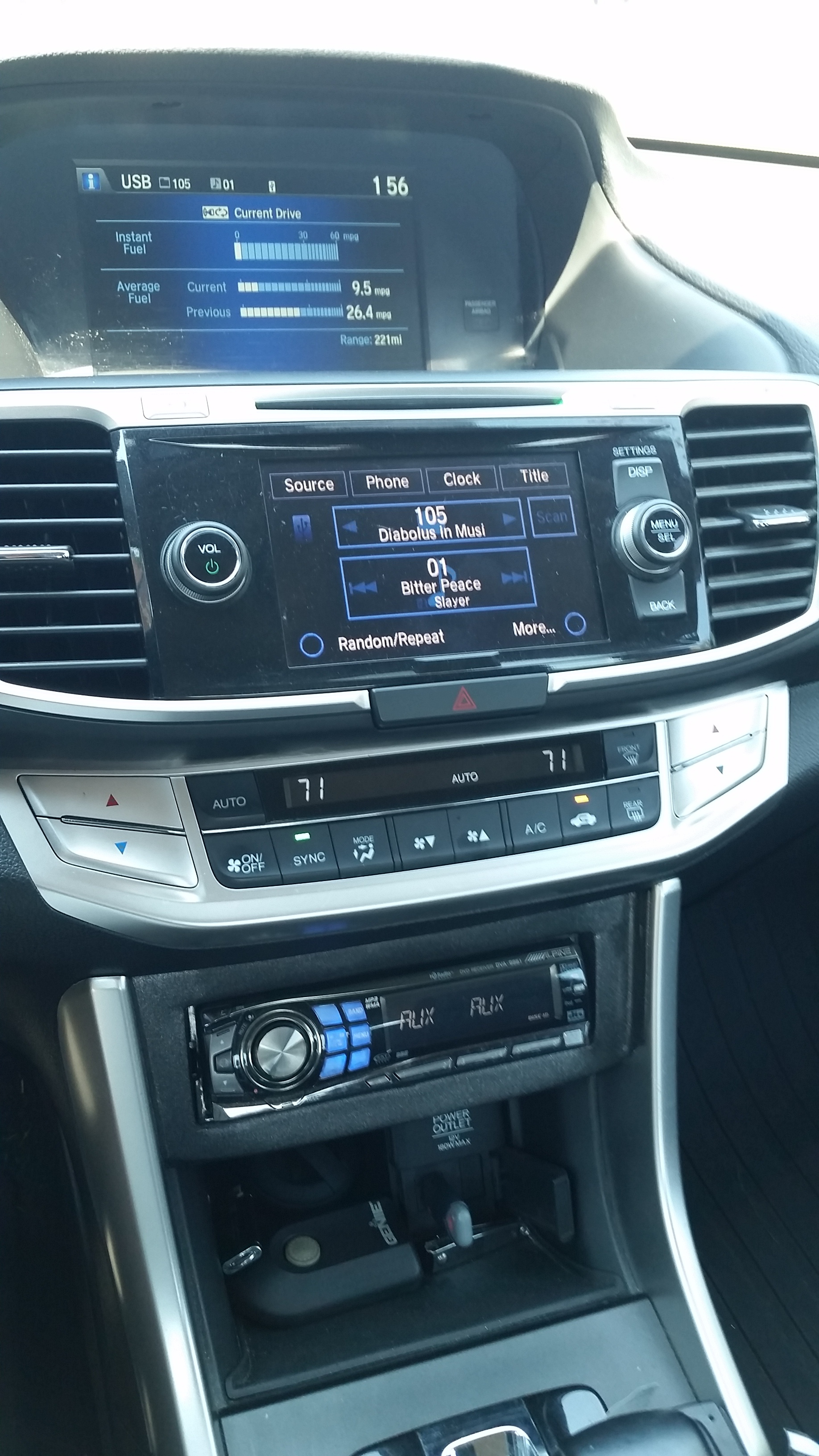
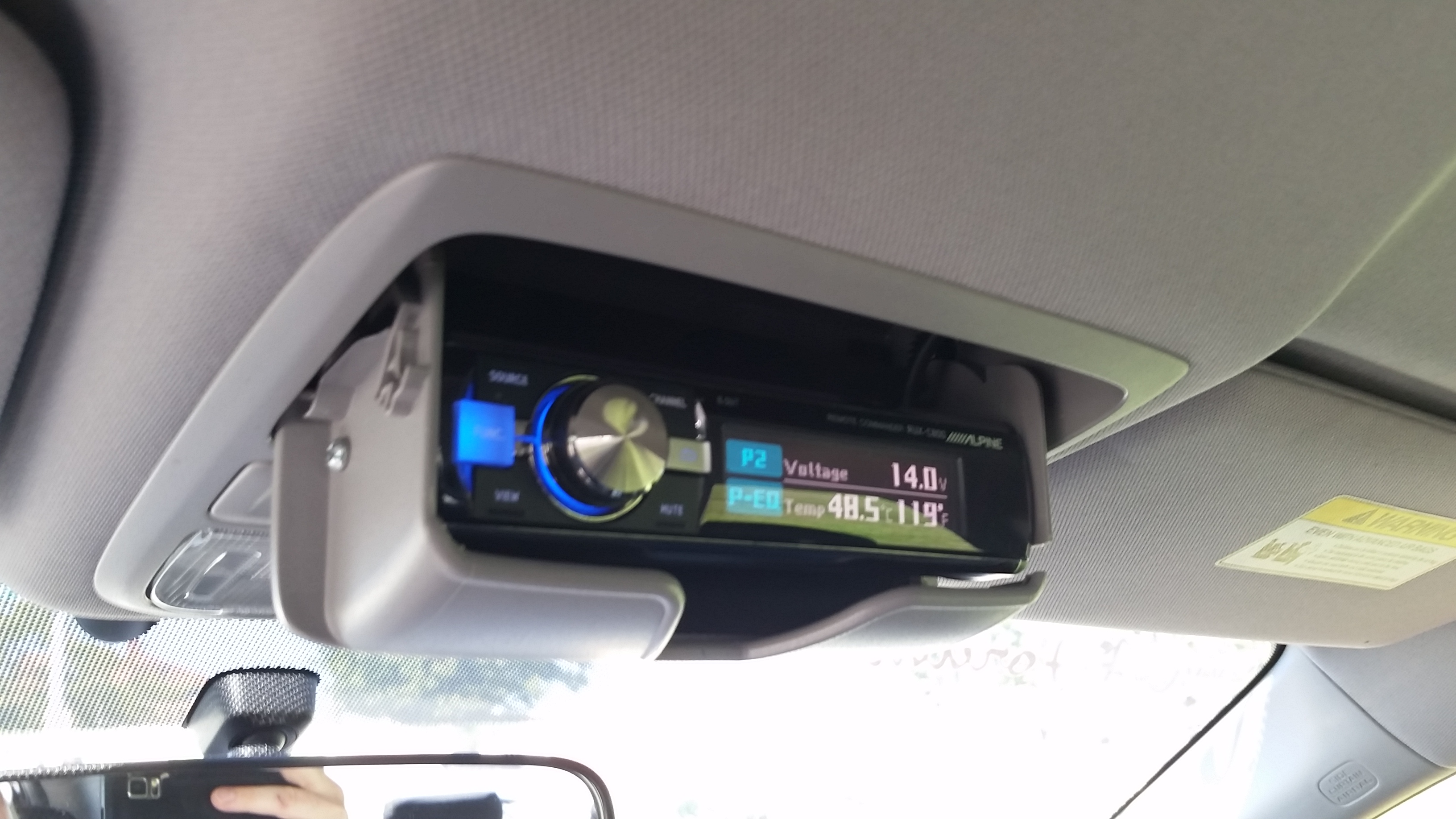
My solution for adding an aftermarket deck included a full custom mount in place of the lower pocket. I added an Alpine CDA-9887 head unit. All of this is also in my build log.
I connected the factory head unit output into the Alpine AUX input through a line output converter. A PAC SWI-JACK allows the steering wheel controls to operate the Alpine. The display button still works on the stock deck.
***DISCLAIMER***
I destroyed the factory pocket to make this mount work. You will need to buy a replacement pocket if you want to return the car to stock. I cut out part of the rear of the plastic dash pieces to gain depth for cabling. Making the mount stick out farther could save some cutting but wouldn't look as nice. If you attempt this, you do so at your own risk and no one on this forum or myself is responsible for any of your actions or damage you may cause.
I removed the pocket, cut it up, and prepped it
cover removed

mockup

cutting. i cut most of the pocket out and just left the face and mounting tabs and bottom. The bottom holds the head unit and keeps it from sagging.

putting the sleeve in


starting the fill process with air dry clay to create the base.

empty dash

PAC SWI-JACK for steering wheel controls.
David Navone Engineering N-RHL2 LOC


I connected the factory head unit output into the Alpine AUX input through a line output converter. A PAC SWI-JACK allows the steering wheel controls to operate the Alpine. The display button still works on the stock deck.
***DISCLAIMER***
I destroyed the factory pocket to make this mount work. You will need to buy a replacement pocket if you want to return the car to stock. I cut out part of the rear of the plastic dash pieces to gain depth for cabling. Making the mount stick out farther could save some cutting but wouldn't look as nice. If you attempt this, you do so at your own risk and no one on this forum or myself is responsible for any of your actions or damage you may cause.
I removed the pocket, cut it up, and prepped it
cover removed
mockup
cutting. i cut most of the pocket out and just left the face and mounting tabs and bottom. The bottom holds the head unit and keeps it from sagging.
putting the sleeve in
starting the fill process with air dry clay to create the base.
empty dash
PAC SWI-JACK for steering wheel controls.
David Navone Engineering N-RHL2 LOC
Thread Starter
|
Super Moderator
Joined: Dec 2009
Posts: 3,279
From: Quad Cities, IL
more work on the mount - some bondo fill (i added fill and sanded the mount at least 7 times when all was said and done)


in process, more sanding and fill followed

test fit
modified the pocket cover to make a HU cover so the addition is stealth when parked


i put neodymium magnets inside the mount as well as on the faceplate behind the foam. they work great and firmly hold the cover on.

current status

nighttime pics

in process, more sanding and fill followed
test fit
modified the pocket cover to make a HU cover so the addition is stealth when parked
i put neodymium magnets inside the mount as well as on the faceplate behind the foam. they work great and firmly hold the cover on.
current status
nighttime pics


Thread Starter
|
Super Moderator
Joined: Dec 2009
Posts: 3,279
From: Quad Cities, IL
The swap to a newer, premium touch screen is mostly done. Not all of the harnesses match up so it took some effort to coordinate the pin-out. For example, harness "F" is needed and requires 12V constant and ground.
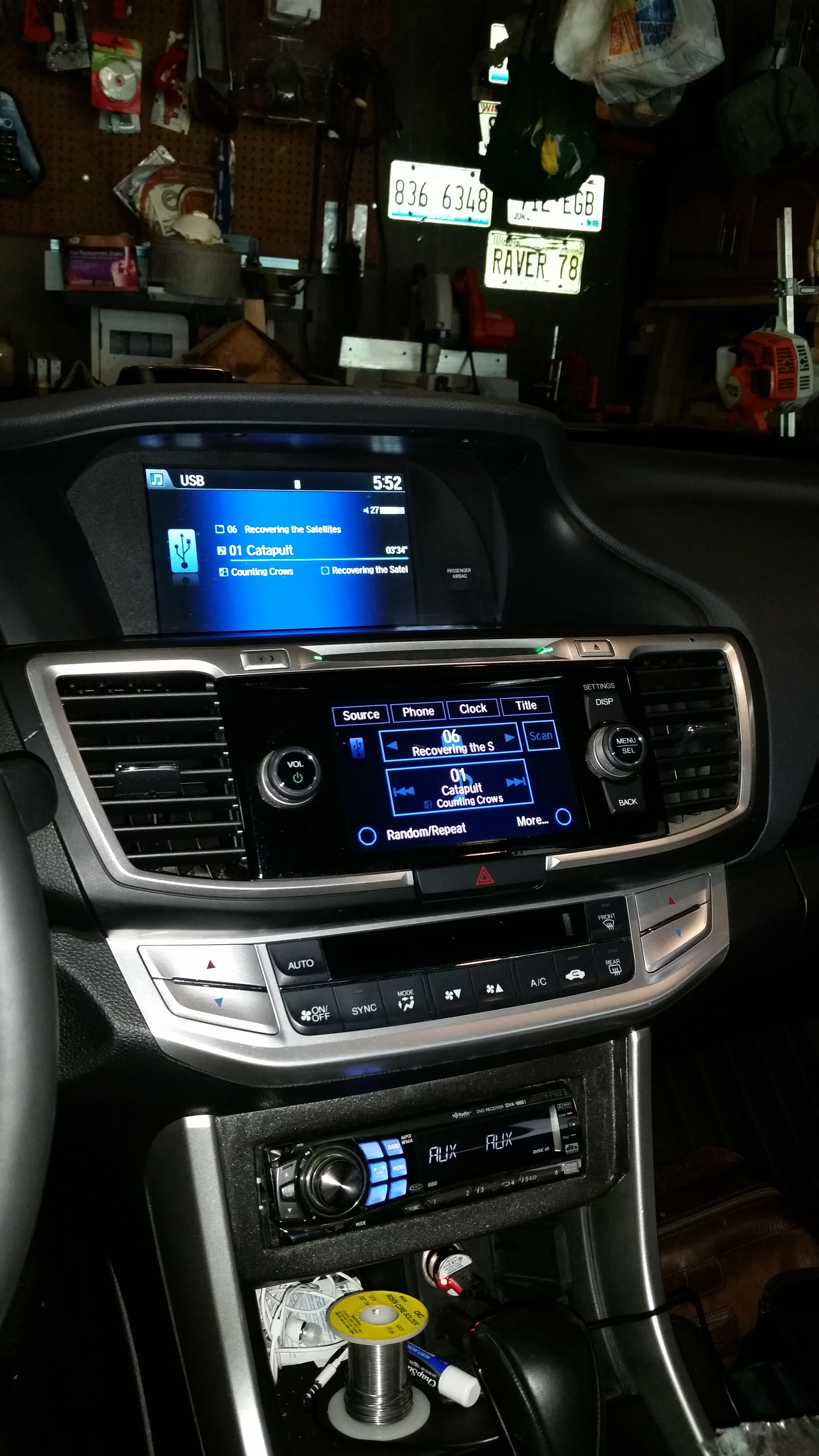
The whole point of the swap is to get a clean signal without DSP and HPF. Mission accomplished. The premium factory HU is made by Alpine and has a clean signal out of the HU (designed to feed an external amp which has DSP). At least Honda had one option that was reasonable.
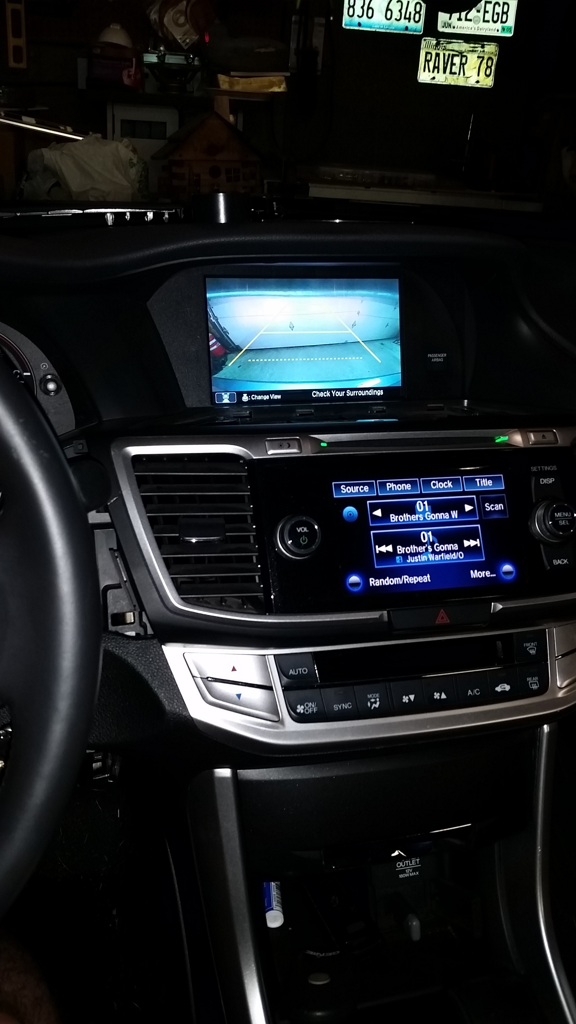
video of function of settings. ignore the hassle with screen visibility initially
Originally, the backup camera didn't work because the premium unit has a wire trigger from the reverse relay. The base model must snag that data via CANbus.
Here is the research and execution of regaining that function:
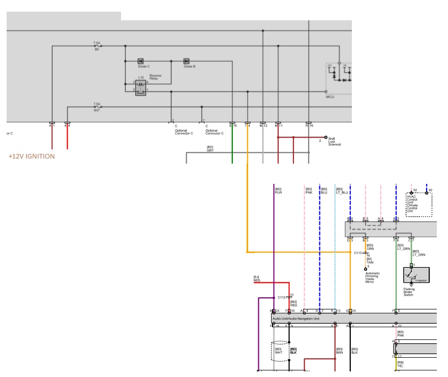
Schematic showing the premium touchscreen HU reverse wire (through relay). HU receives a +12V switched signal when in reverse.
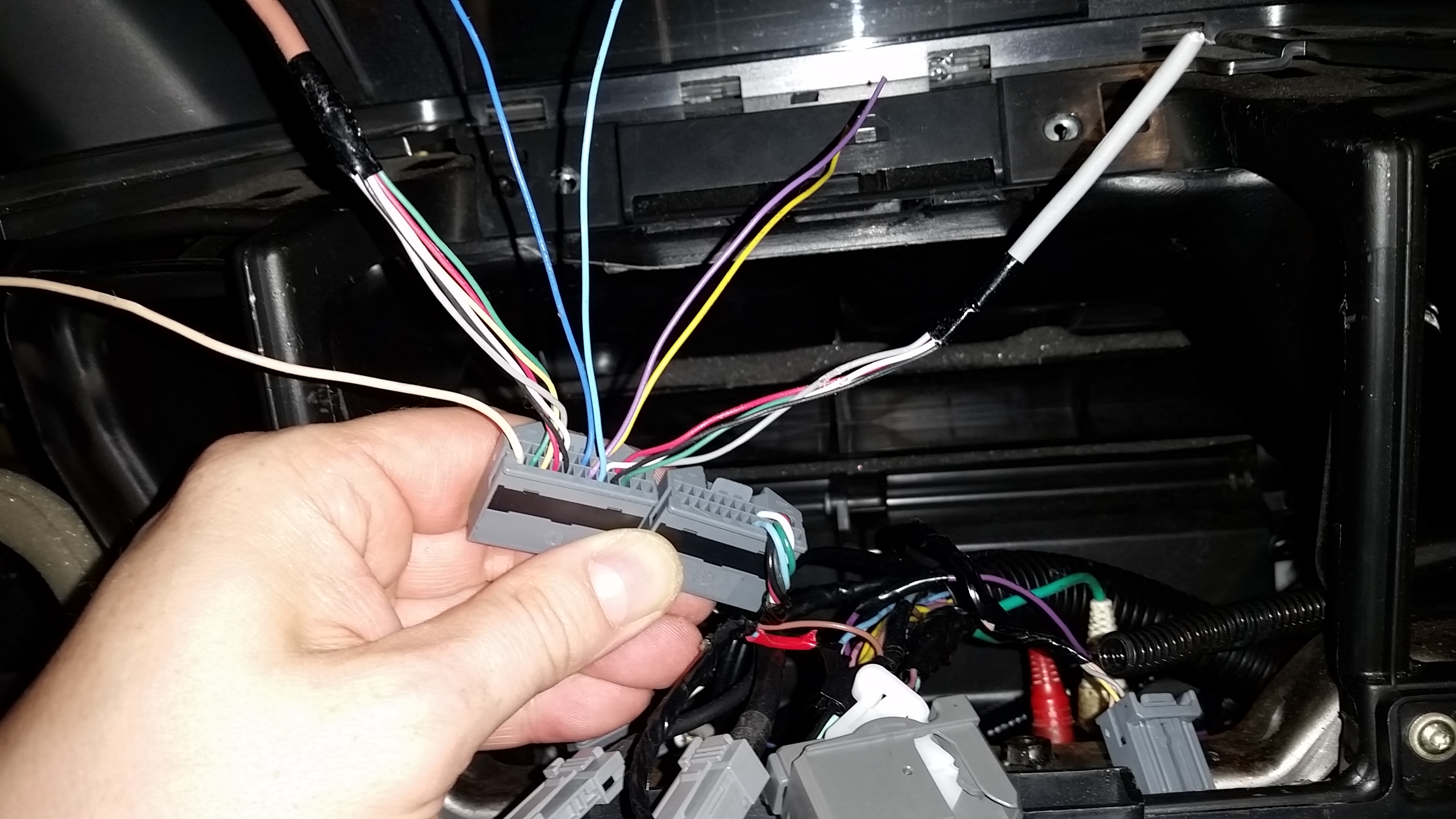
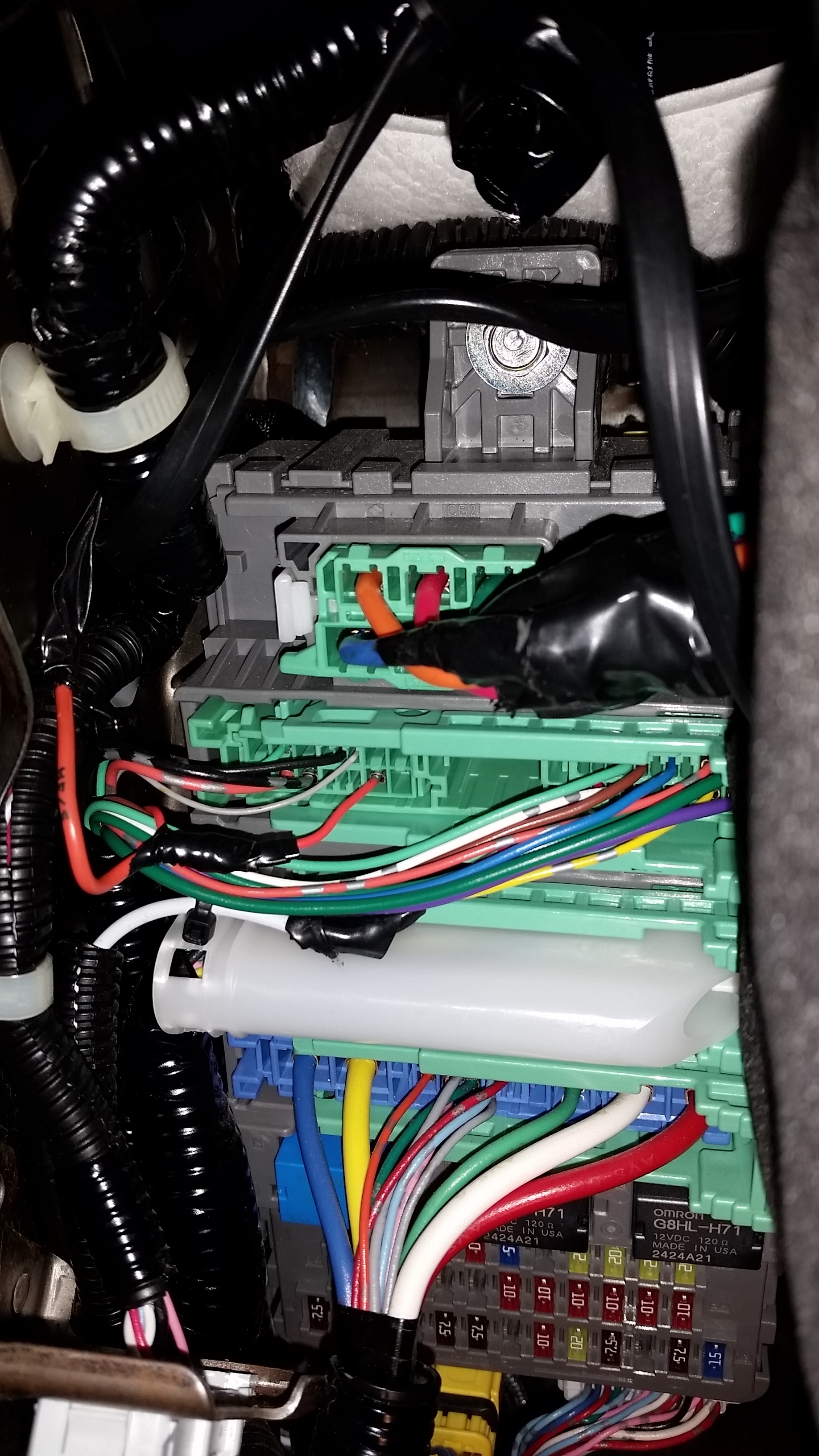
comparison of premium HU harness "G" (left) and Sport harness "G" (right). notice missing wires, especially bottom left G24
when searching for the reverse wire, i figured the DirectWire2.0 information (used for remote start install) would be handy, i was correct
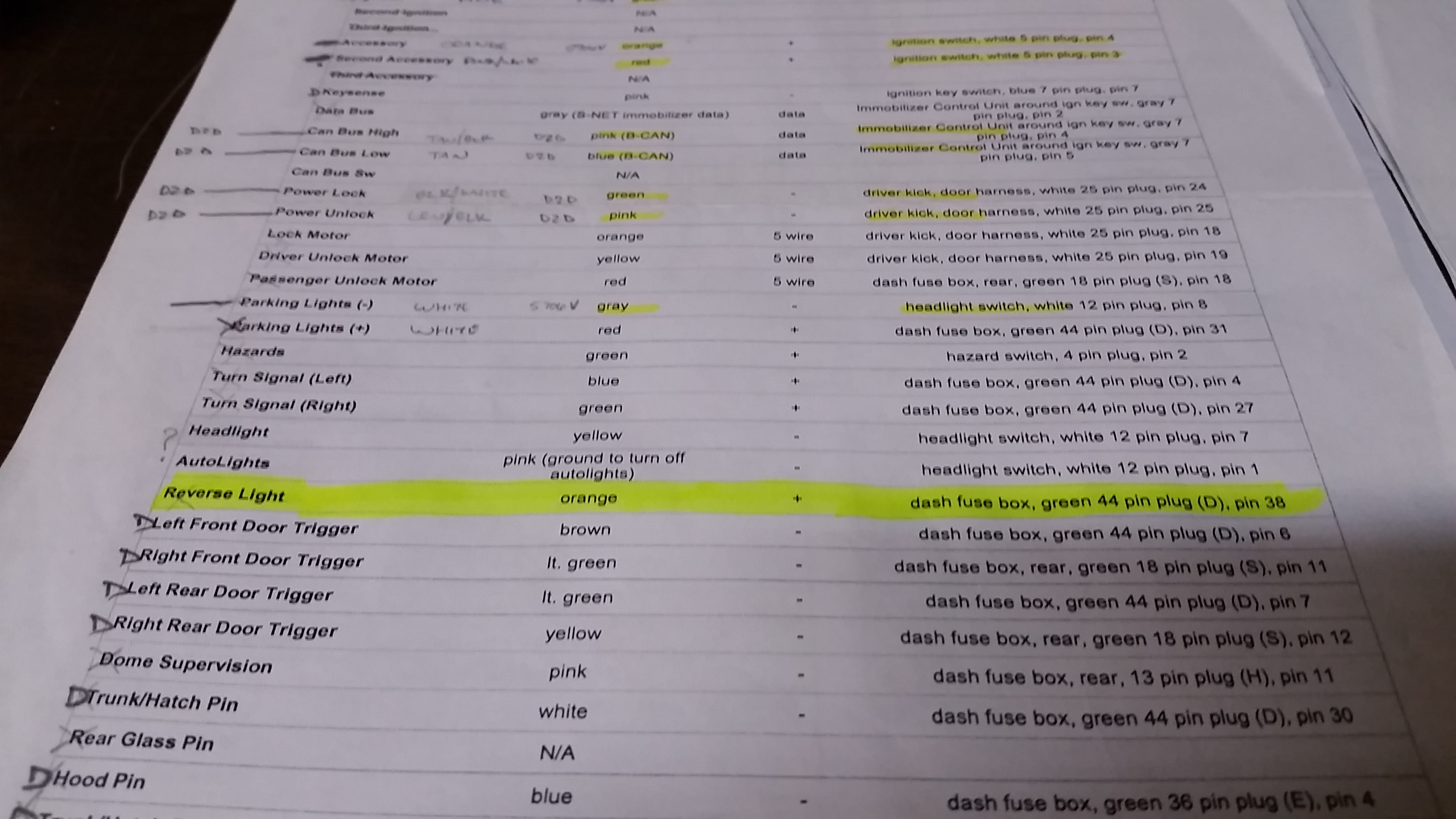
Harness "D" has is in the main driver's side harness and Pin D38 has an orange wire used for reverse switched +12V.
here the wire is intercepted and soldered:
taped and secured
pin added to harness at HU
success

Thread
Thread Starter
Forum
Replies
Last Post
hondalearner
General Tech Help
2
Mar 24, 2015 05:54 AM
Pissedoffbumblebee
PRIVATE For Sale / Trade Classifieds
2
Jul 24, 2013 01:21 AM
Queen eiko
General Tech Help
0
Jan 24, 2010 12:09 AM
rpreziosi
General Tech Help
4
Jan 2, 2010 09:27 PM
Antarctica
Appearance
11
Jul 10, 2008 02:48 AM