
Honda Electrical Load Detection (ELD) Bypass


Thread Starter
|
Super Moderator
Joined: Dec 2009
Posts: 3,279
From: Quad Cities, IL
I'll start by saying that I am not a Honda technician or representative. I'm an Electrical Engineer with an emphasis in digital and analog circuit design - which required a lot of circuit construction and design both as part of my degree and my personal hobby of designing and building circuits. I also do this for fun.
My 2001 Honda Accord started having electrical issues. I figured out that the Electronic Load Detection (ELD) circuit was responsible for a drop in voltage that seemed "random". While driving, my voltage would drop from >14 VDC to 12.6 VDC and then down to 11.9 VDC with my sound system on loud. My stock alt was 105A and I figured I was taxing my alt, and the system + car was more current than the stock alt was producing. I upgraded to a 140A high output alternator and re-did my big 3 alt power.
While doing this upgrade I started doing a lot of research on Honda alternators, but I didn’t come across anything about the ELD.
After the alternator installation I did a test drive with my DMM reading the battery voltage, and I noticed a nice 14.6 VDC for the first three blocks (no ignition loads on). Then the voltage dropped to 12.8 VDC again. Then I noticed it came back up and stayed up with the A/C on. This prompted more research and I came across ELD posts. Ah Ha!! I expected to find a good solution, but alas, there was none. No one was offering up solutions other than replacing the ECU or cutting wires and leaving them open. Not acceptable.
I decided to develop a solution. And through my posts on Sound Domain with other members, I talked my way through an idea. I’m sharing this solution with all of you, because I believe knowledge should be shared.
The concept of the ELD as follows. The powertrain control module accepts an input from the ELD. The ELD senses current on the 50A ignition wire in the engine fuse box. The ELD gives information to the PCM with a DC voltage between 1.1-5 VDC. The higher the number, the lower the load, and vice versa. So when the sensing voltage stays above 2.5-2.8 VDC, the PCM tells the alternator to turn off. The voltage drops to the battery float voltage, and your fuel mileage goes up. This trick saves you fuel, but you lose alternator power. This is an issue to all of us with sound systems because the system only senses current through the ignition system. Anything connected directly to the battery is ignored. You can’t add your load to the ignition system because that system is already maxed out. No additional load should be supplied to the ignition system.
When the ELD sensing voltage decreases to around 2.1 VDC or lower, this tells the PWM that the ignition load is high, so the alternator kicks back on to full output and your voltage increases to >14 VDC. You don’t want to just turn on the A/C all the time because that also puts load on the engine and electrical system. You don’t want to just cut wiring and leave the alt in full output mode all of the time because it will shorten the life of your battery and alternator. Cutting wires can also throw codes to the ECU and we prefer to leave our check engine light off.
You are performing this modification at your own risk. Your local dealer may think you're crazy for wanting to do this, and they may tell you it will damage your car as a CYA for themselves. You don't want to make a mistake and damage your powertrain control module. You must be VERY CAREFUL making these modifications. Triple check all wiring connections and always disconnect the battery negative before performing any electrical modifications.
Last edited by keep_hope_alive; May 19, 2018 at 07:06 PM.
Thread Starter
|
Super Moderator
Joined: Dec 2009
Posts: 3,279
From: Quad Cities, IL
My circuit is the best compromise I can think of without building a custom circuit that actually senses the audio system load. This is a manual/automatic system for overriding the ELD signal. It works like this: The resistance seen by the PWM at the ELD is what determines the voltage drop from the 5 VDC produced by the PWM. I have a relay that switches between the ELD resistance, and a fixed 820 ohm resistor tied to ELD ground (NOT CHASSIS GROUND). Do not ground this resistor to chassis ground. Do not ground this resistor to chassis ground. Got it? Good.  This relay could just be controlled with a switch, but that isn’t enough for me. I am powering the relay coil from the Head Unit remote turn-on (blue/white wire) and grounding the relay coil with a toggle switch at the dash. This means that in order to bypass the ELD, we need both the Head Unit on and toggle switch closed. The idea is that we are doing this for our sound system but we still want fuel and battery savings when we’re not cranking tunes. This is common for me with kids and phone calls (Bluetooth). We could just control the relay from the head unit, but the toggle switch lets us also save fuel with low volume listening sessions (kids, family, coworkers, etc.). It requires that you are paying attention to the vehicle, the voltage, and your system usage. Later, I will develop a solution that monitors the sound system and triggers the relay with 20-40A of usage.
Onto the circuit design.
Parts List:
(1) 20A 12VDC relay, with 12VDC coil and N.O and N.C. contacts (5-pin) – I recommend getting a 5-wire socket with it.
(1) 820 Ohm Resistor (Gray/Red/Brown)
(1) 12VDC SPST Toggle Switch (unlit – a lit toggle would need separate terminals for the lamp)
Approximately 10 feet of 18awg wiring – each 10 ft. in three colors for a total of 30 ft. I found that 10 feet of 18-4 CL2 speaker wire works great.
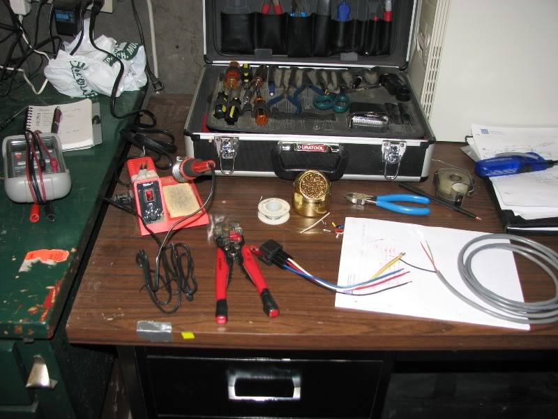
Tools List:
Wire cutters/strippers
Digital Multi Meter (DMM) or volt-meter.
30-40W Soldering Iron and solder (soldering is recommended over crimp terminals)
Heat shrink and electrical tape.
Wire connectors - ring terminal for ground, butt connector for remote.
Haynes manual with wiring diagrams to verify your specific system wire colors
Areas of access:
Engine bay – main fuse panel
Dash – removal of head unit and access under dash
Firewall – path for cabling (determines wiring length)
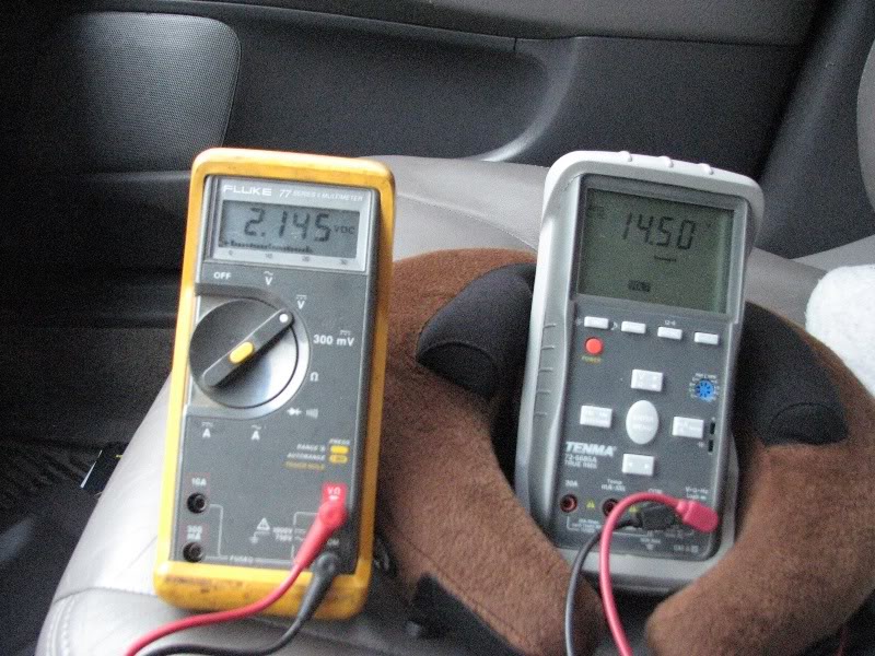
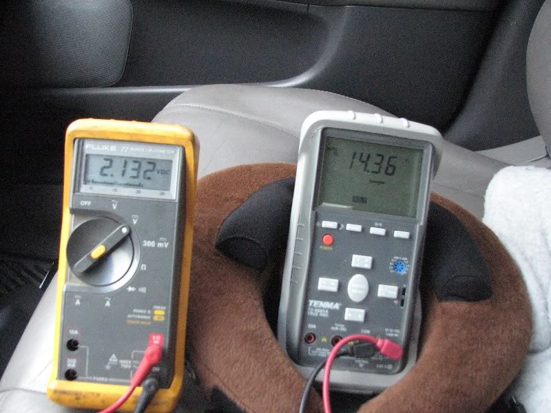
Some DMM images to explain what is going on:
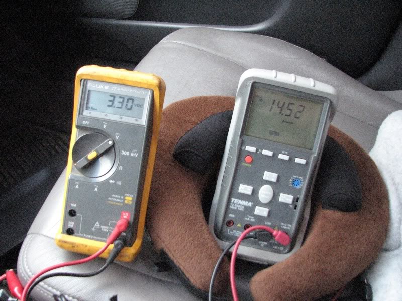
Gray DMM on the Right is Battery Voltage
Yellow DMM on the Left is the ELD voltage seen by the PCM
In these, the Accord is idling at 800 RPM in the driveway after sitting for a day. I turn on and off loads to monitor the ELD sense voltage and the battery voltage. In this example, the alternator did not turn off, that requires more time and some driving around.
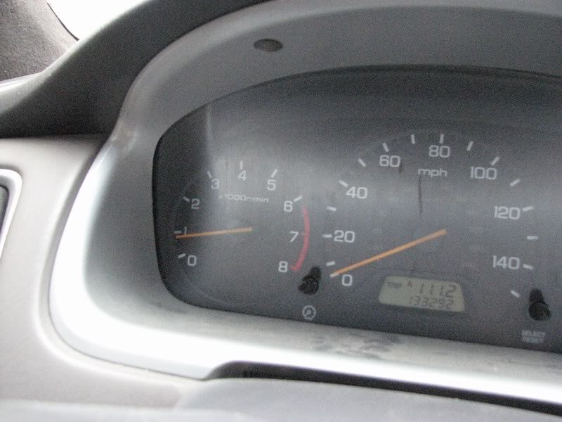
Image of tach position for all of these photos:
Example while driving, alternator is on, 3.3 VDC indicates little ignition load
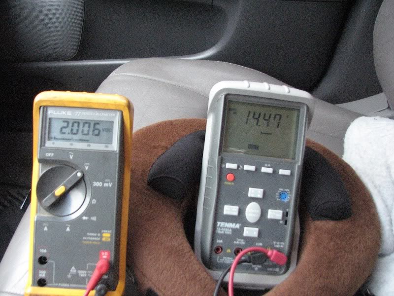
Then I turn the A/C on and the ELD sense voltage drops to 2.0 VDC. The alt is on because the car just started and the ECU waits a bit to charge the battery.
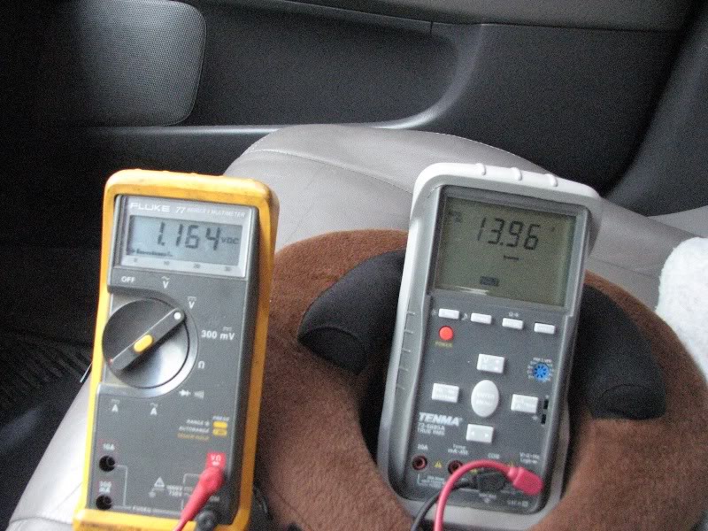
Now the A/C and rear defrost are on, and the ELD sense voltage drops to 1.16 VDC and the battery voltage is down to 13.96 VDC with the alt still on. The stereo is off – this is why a stock alternator can have a hard time keeping up with a sound system at idle.
Now I engage my circuit, and the ELD sense voltage drops to the design ~2.1 VDC (due to the 820 ohm resistor). This will always turn the alt on and keep it on.
Now the A/C is on, the stereo is on (high listening volume) and the engine at 800 RPM idle (with ELD bypass engaged)
This relay could just be controlled with a switch, but that isn’t enough for me. I am powering the relay coil from the Head Unit remote turn-on (blue/white wire) and grounding the relay coil with a toggle switch at the dash. This means that in order to bypass the ELD, we need both the Head Unit on and toggle switch closed. The idea is that we are doing this for our sound system but we still want fuel and battery savings when we’re not cranking tunes. This is common for me with kids and phone calls (Bluetooth). We could just control the relay from the head unit, but the toggle switch lets us also save fuel with low volume listening sessions (kids, family, coworkers, etc.). It requires that you are paying attention to the vehicle, the voltage, and your system usage. Later, I will develop a solution that monitors the sound system and triggers the relay with 20-40A of usage. Onto the circuit design.
Parts List:
(1) 20A 12VDC relay, with 12VDC coil and N.O and N.C. contacts (5-pin) – I recommend getting a 5-wire socket with it.
(1) 820 Ohm Resistor (Gray/Red/Brown)
(1) 12VDC SPST Toggle Switch (unlit – a lit toggle would need separate terminals for the lamp)
Approximately 10 feet of 18awg wiring – each 10 ft. in three colors for a total of 30 ft. I found that 10 feet of 18-4 CL2 speaker wire works great.
Tools List:
Wire cutters/strippers
Digital Multi Meter (DMM) or volt-meter.
30-40W Soldering Iron and solder (soldering is recommended over crimp terminals)
Heat shrink and electrical tape.
Wire connectors - ring terminal for ground, butt connector for remote.
Haynes manual with wiring diagrams to verify your specific system wire colors
Areas of access:
Engine bay – main fuse panel
Dash – removal of head unit and access under dash
Firewall – path for cabling (determines wiring length)
Some DMM images to explain what is going on:
Gray DMM on the Right is Battery Voltage
Yellow DMM on the Left is the ELD voltage seen by the PCM
In these, the Accord is idling at 800 RPM in the driveway after sitting for a day. I turn on and off loads to monitor the ELD sense voltage and the battery voltage. In this example, the alternator did not turn off, that requires more time and some driving around.
Image of tach position for all of these photos:
Example while driving, alternator is on, 3.3 VDC indicates little ignition load
Then I turn the A/C on and the ELD sense voltage drops to 2.0 VDC. The alt is on because the car just started and the ECU waits a bit to charge the battery.
Now the A/C and rear defrost are on, and the ELD sense voltage drops to 1.16 VDC and the battery voltage is down to 13.96 VDC with the alt still on. The stereo is off – this is why a stock alternator can have a hard time keeping up with a sound system at idle.
Now I engage my circuit, and the ELD sense voltage drops to the design ~2.1 VDC (due to the 820 ohm resistor). This will always turn the alt on and keep it on.
Now the A/C is on, the stereo is on (high listening volume) and the engine at 800 RPM idle (with ELD bypass engaged)
Last edited by keep_hope_alive; Jun 1, 2010 at 01:40 AM.
Thread Starter
|
Super Moderator
Joined: Dec 2009
Posts: 3,279
From: Quad Cities, IL
Wiring Schematic:
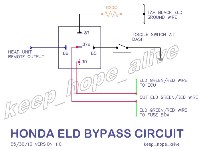
* It is important that Relay Terminal 30 is connected to the PCM/ECU side of the Green/Red wire cut. This corresponds to the blue wire in the relay socket.
* The normally closed (N.C.) position Relay Terminal 87a is connected to the ELD side of the Green/Red wire cut. This corresponds to the Red wire of the relay socket.
* The normally open (N.O.) position Relay Terminal 87 has an 820 ohm resistor on it that is in series with the tap of the Black ELD wire. This corresponds to the Yellow wire of the relay socket.
* The relay coil terminal 86 is wired to the head unit remote turn-on output (12VDC) This corresponds to the white wire of the relay socket.
* The relay coil terminal 85 is wired to the toggle switch. This corresponds to the Black wire of the relay socket.
* The other terminal on the toggle switch is tied to chassis ground – I used the head unit ground.
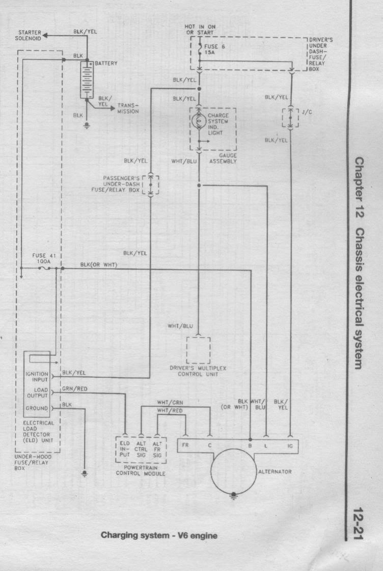
This is the factory wiring diagram (taken from Haynes manual):
* It is important that Relay Terminal 30 is connected to the PCM/ECU side of the Green/Red wire cut. This corresponds to the blue wire in the relay socket.
* The normally closed (N.C.) position Relay Terminal 87a is connected to the ELD side of the Green/Red wire cut. This corresponds to the Red wire of the relay socket.
* The normally open (N.O.) position Relay Terminal 87 has an 820 ohm resistor on it that is in series with the tap of the Black ELD wire. This corresponds to the Yellow wire of the relay socket.
* The relay coil terminal 86 is wired to the head unit remote turn-on output (12VDC) This corresponds to the white wire of the relay socket.
* The relay coil terminal 85 is wired to the toggle switch. This corresponds to the Black wire of the relay socket.
* The other terminal on the toggle switch is tied to chassis ground – I used the head unit ground.
This is the factory wiring diagram (taken from Haynes manual):
Thread Starter
|
Super Moderator
Joined: Dec 2009
Posts: 3,279
From: Quad Cities, IL
Construction of the circuit:
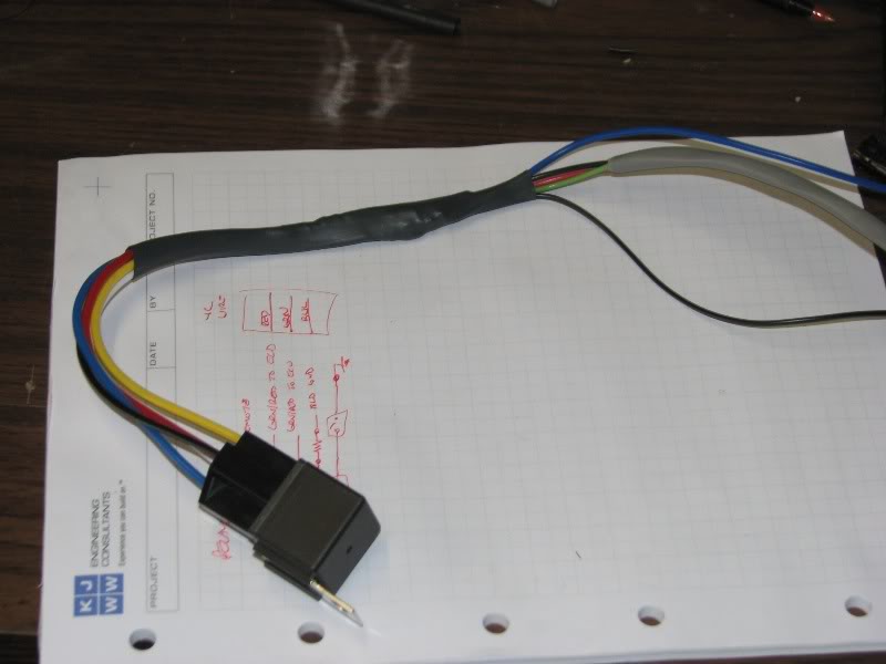
I used a relay socket with wires to save myself some work, and allow for quick replacement if/when the relay fails.
The setup in my garage used for making this:
Wires soldered with heat shrink:
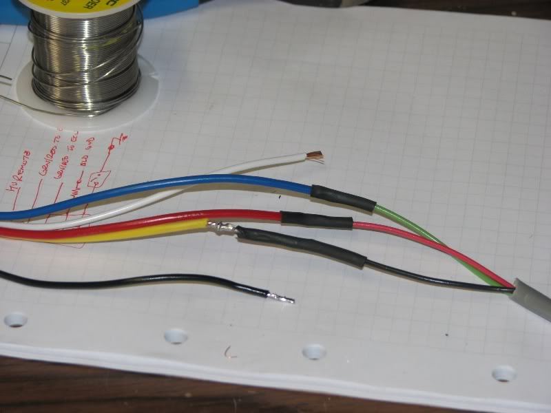
Heat shrink over the whole assembly
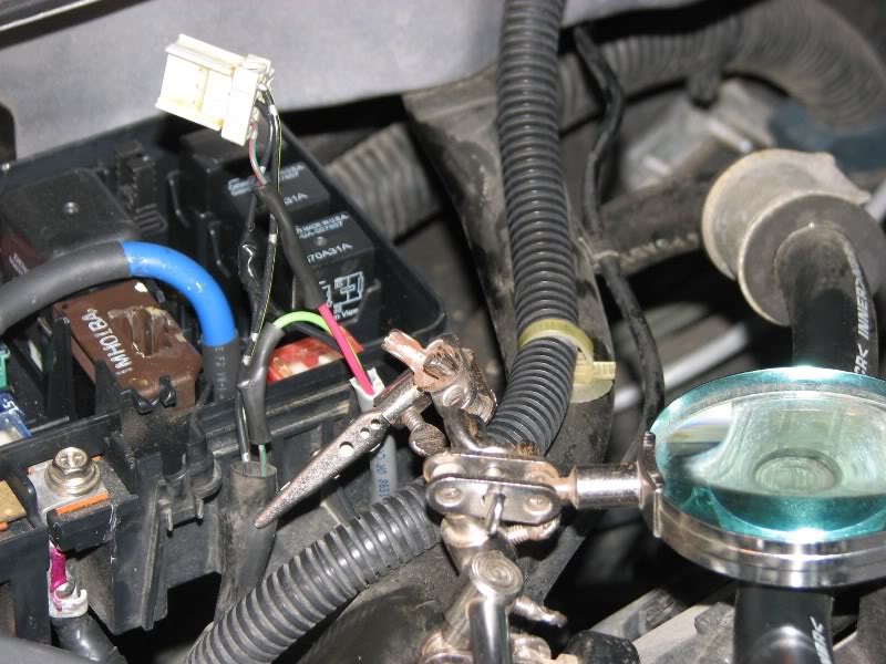
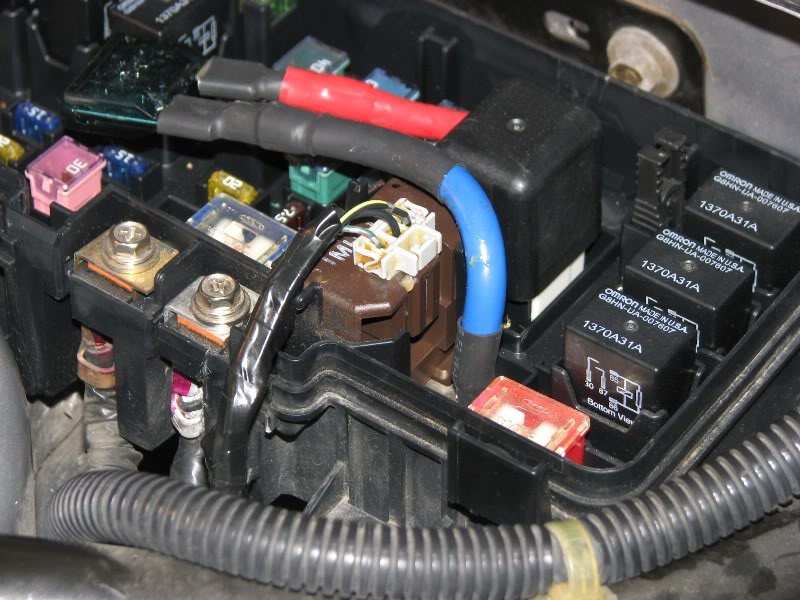
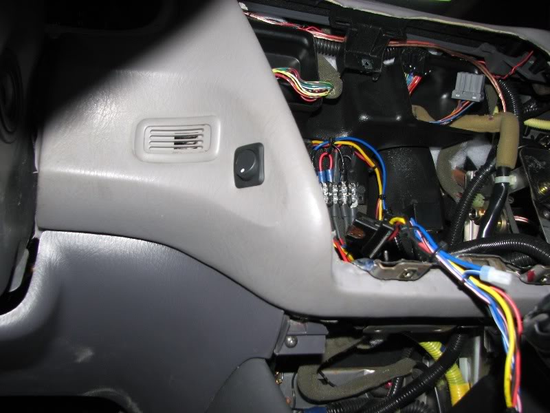
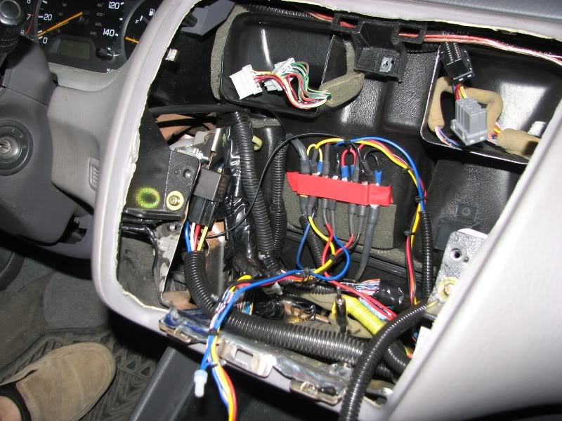
In the engine bay:
Green/Red ELD wire cut. Wires on either side - Green into the PCM and Red into the ELD. Black tapped to Black ELD ground (Not Chassis Ground).
Wires soldered, heat shrunk and taped:
Taped entire assembly:
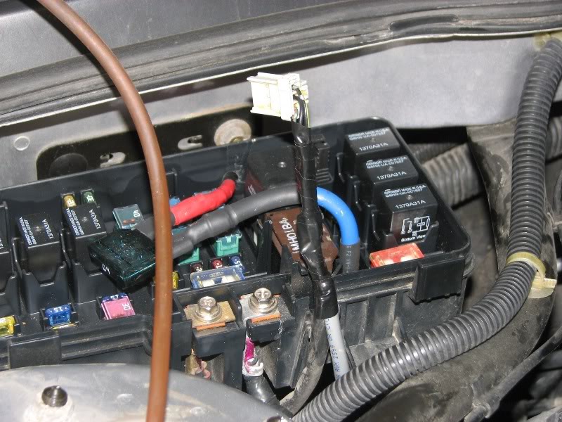
Plugged back into the ELD and routed in the same place. You could make your taps lower and save some hassle with the cover:
Fuse box cover on, new wiring routed in 1/2" high heat split loom, zip tied to strut tower bar and routed along fire wall:
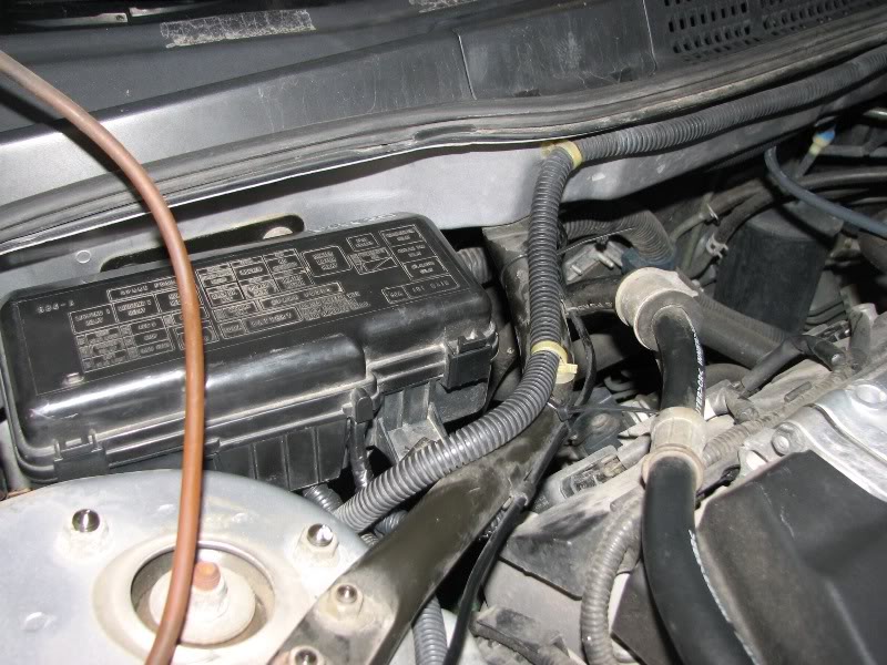
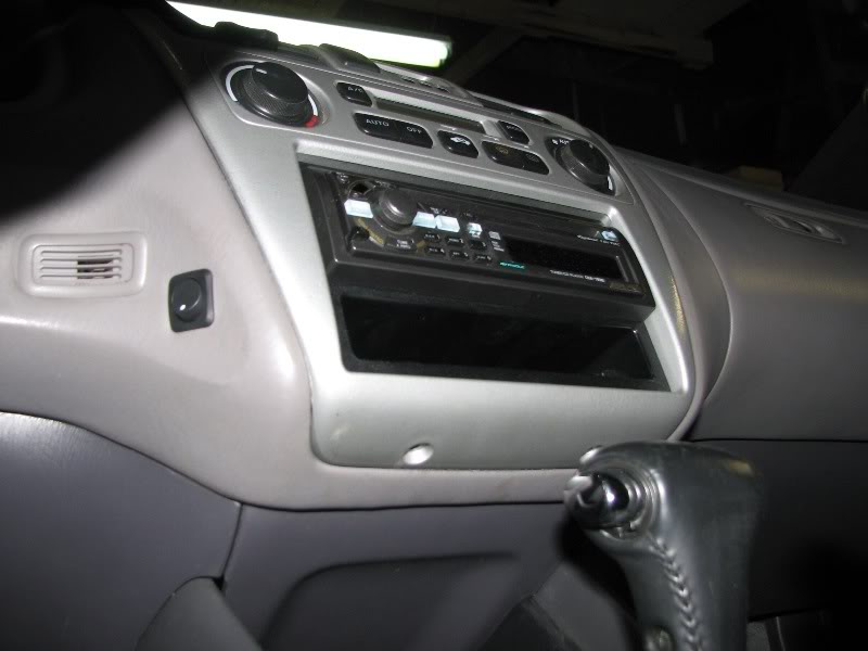
In the dash:
Relay mounted in dash, wiring in split loom. The wiring terminal on the back wall is providing some other functionality for head unit power (10 awg power from battery powers head unit and dash accessories, with a relay switched from factory radio ignition). I have landed my remote wire turn-on lead and relay coil ground lead here:
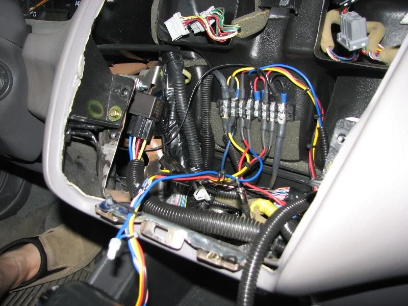
Installation of override switch (convenient and accessible yet out of the way):
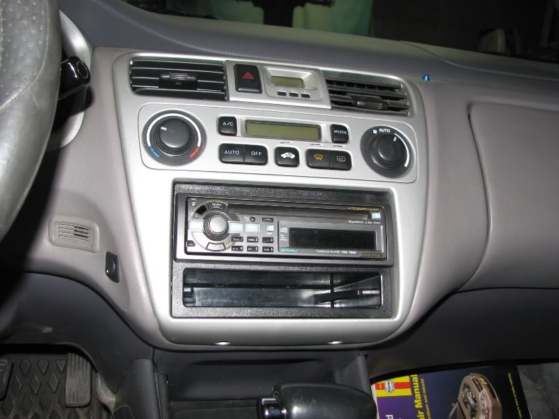
Terminal taped over and remote wire in split loom. Final installation in dash:
Everything re-assembled:
I used a relay socket with wires to save myself some work, and allow for quick replacement if/when the relay fails.
The setup in my garage used for making this:
Wires soldered with heat shrink:
Heat shrink over the whole assembly
In the engine bay:
Green/Red ELD wire cut. Wires on either side - Green into the PCM and Red into the ELD. Black tapped to Black ELD ground (Not Chassis Ground).
Wires soldered, heat shrunk and taped:
Taped entire assembly:
Plugged back into the ELD and routed in the same place. You could make your taps lower and save some hassle with the cover:
Fuse box cover on, new wiring routed in 1/2" high heat split loom, zip tied to strut tower bar and routed along fire wall:
In the dash:
Relay mounted in dash, wiring in split loom. The wiring terminal on the back wall is providing some other functionality for head unit power (10 awg power from battery powers head unit and dash accessories, with a relay switched from factory radio ignition). I have landed my remote wire turn-on lead and relay coil ground lead here:
Installation of override switch (convenient and accessible yet out of the way):
Terminal taped over and remote wire in split loom. Final installation in dash:
Everything re-assembled:
Last edited by keep_hope_alive; Jun 1, 2010 at 01:33 AM.

Joined: Mar 2011
Posts: 4
I've had the same symptoms and problems with my '99 Accord, and I'd like to install a simple manual bypass switch. I don't have a monster sound system, but I'd like to have control over the alternator, just the same.
If I interpret your diagram correctly, a simple SPDT toggle switch would work if wired like this:
1. Cut ELD green/red wire as in your circuit.
2. The half of that wire coming from the PCM goes to the POLE of the toggle switch.
3. The other half goes to one of the THROWS of the switch; the POLE would be switched to this THROW when I want to ELD to work normally.
4. The other THROW goes through an 820-ohm resistor to the black ELD ground wire at the plug; switching to this THROW would bypass the ELD and cause the alternator to turn on and charge the battery all the time.
QUESTIONS:
1. Am I correct above?
2. Are there any problems lengthening the green/red wire between the PCM and the ELD?
Thanks for an excellent idea.
Thread Starter
|
Super Moderator
Joined: Dec 2009
Posts: 3,279
From: Quad Cities, IL
Yes your idea would work and not include head unit remote output.
820 ohm worked for me, should be universal, but measure voltage just to ensure you get sufficient drop. A volt meter in the car is a good idea.
820 ohm worked for me, should be universal, but measure voltage just to ensure you get sufficient drop. A volt meter in the car is a good idea.
Joined: Mar 2011
Posts: 4
Incidentally, I asked my Honda service manager about posts I've seen here and elsewhere claiming that running the alternator all the time is bad for both the alternator and the battery. Nonsense! Consider all the millions of cars WITHOUT any sort of ELD system, cars whose alternators run all the time by design.
Last edited by Richard in Florida; Mar 8, 2011 at 09:29 AM.
Joined: Mar 2011
Posts: 4
For the life of me I can't come up with an 820 ohm resistor. Is there any risk attached to trying a 1K? Is 1/2 watt robust enough?
Joined: Mar 2011
Posts: 4
To test the bypass idea in my '99 Accord V6 I came up with this simple idea that takes one minute to try. Check the photo.
Because I didn't have the prescribed 820-ohm resistor on hand, I used a 1K and a 4.7K in parallel which is very close.
I removed the plug from the ELD itself inside the under-hood fusebox. Now the ELD is out of the car's electrical system.
I pushed one resistor lead into green/red wire terminal on the wire end of the connector, and I pushed the other resistor lead into the black wire terminal.
I left the plug loose, NOT plugged back into the ELD. There's plenty of room inside the fusebox to safely tuck away the loose connector.
My alternator now runs all the time, ranging from 14.00 to 14.75. Time will tell, but so far I think I like the difference.
This lash-up is temporary, certainly not something you'd want to leave in place forever.
Thread Starter
|
Super Moderator
Joined: Dec 2009
Posts: 3,279
From: Quad Cities, IL
The ELD is a fuel saving measure. It is another input for the ECM for alternator field control. I agree having it on all of the time should be fine. I just like the option of increasing mpg when possible.
In a new carn this mod is llikely to void your warranty.
820 ohms is a standard value that gave me the necessary voltage drop.
In a new carn this mod is llikely to void your warranty.
820 ohms is a standard value that gave me the necessary voltage drop.