
High beam Relay location


Thread Starter
|
Junior Member
Joined: Sep 2014
Posts: 39
I like to reinvent wheel. 
I am planning to retrofit BI xenons in my 2005 Accord and convert high beams to DRL with LED bulbs. Didnt want to buy any module etc and i have a theoretical circuit ready.
Hope u got an idea.
I am planning to retrofit BI xenons in my 2005 Accord and convert high beams to DRL with LED bulbs. Didnt want to buy any module etc and i have a theoretical circuit ready.
Hope u got an idea.

Super Moderator
Joined: Dec 2009
Posts: 3,279
From: Quad Cities, IL
the ignition switch is a resistor-based network so you won't be able to just tap into those wires. the ECM looks at the ignition switch for voltage drop and that tells it what position the key is in. this is common because it saves a lot of wiring cost so mfr's have been doing it for a while now.
your best bet (without cutting up the factory control module) is to just snag the outputs of the factory relays and redirect them. you can also tap a wire in the fuse box that is energized with the key in the II position. that gives you three 12V outputs that your circuit can manipulate. then power the lights from a dedicated wiring source to the battery and add a fuse for each output.
your best bet (without cutting up the factory control module) is to just snag the outputs of the factory relays and redirect them. you can also tap a wire in the fuse box that is energized with the key in the II position. that gives you three 12V outputs that your circuit can manipulate. then power the lights from a dedicated wiring source to the battery and add a fuse for each output.
Thread Starter
|
Junior Member
Joined: Sep 2014
Posts: 39
Thanks a lot. Im a newbe and have no idea where to find those circuits. Can u please tell me in detail? Also a pic will be really helpful.
The pic that u have posted, is it an existing module or do I have add one?
The pic that u have posted, is it an existing module or do I have add one?
Super Moderator
Joined: Dec 2009
Posts: 3,279
From: Quad Cities, IL
look for the circuits at the lights - there is no guessing that way. the bulbs are dumb and just respond to voltage. use a DMM to verify voltage on the wiring so you verify which ones to use for +12V and which to use for ground.
all connections should be soldered and then protected in heat shrink and then split loom and then zip tied every 8" or so to existing wire tie points. follow factory wiring routes.
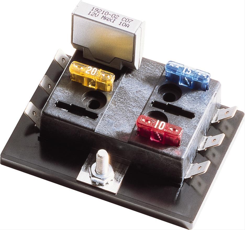
the pic i posted is a product for sale at most major autoparts stores (Autozone, O'Rilley, etc.).
all connections should be soldered and then protected in heat shrink and then split loom and then zip tied every 8" or so to existing wire tie points. follow factory wiring routes.
the pic i posted is a product for sale at most major autoparts stores (Autozone, O'Rilley, etc.).
Thread Starter
|
Junior Member
Joined: Sep 2014
Posts: 39
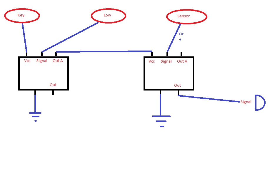
Diagram is for DRL. This is just a draft version. Its a five pin relay. If I can't get the light sensor then I would connect it to 12V directly. The output will be fed to high beam light. I would replace the halogen bulbs with LEDs as it produces less light (so no need for additional circuits to reduce the power of the bulb).
Will connect the high beam switch output to Bi-Xenon's solenoid. So they both will work independently.
Please let me know if it looks good or do I have to make some more changes?
Super Moderator
Joined: Dec 2009
Posts: 3,279
From: Quad Cities, IL
that's not how i draw up relays - though i think i know what you're doing - is "out a" a normally open or normally closed output?
write out the sequence as well. i.e. with key in " " position and light control switch in " " position, DRL is " "
http://www.the12volt.com/relays/relays.asp
write out the sequence as well. i.e. with key in " " position and light control switch in " " position, DRL is " "
http://www.the12volt.com/relays/relays.asp