
Does anyone have an ECU pinout for a 94 LX?


Super Moderator
Joined: Sep 2006
Posts: 16,335
From: Houston, TX
I am not sure what you are asking.
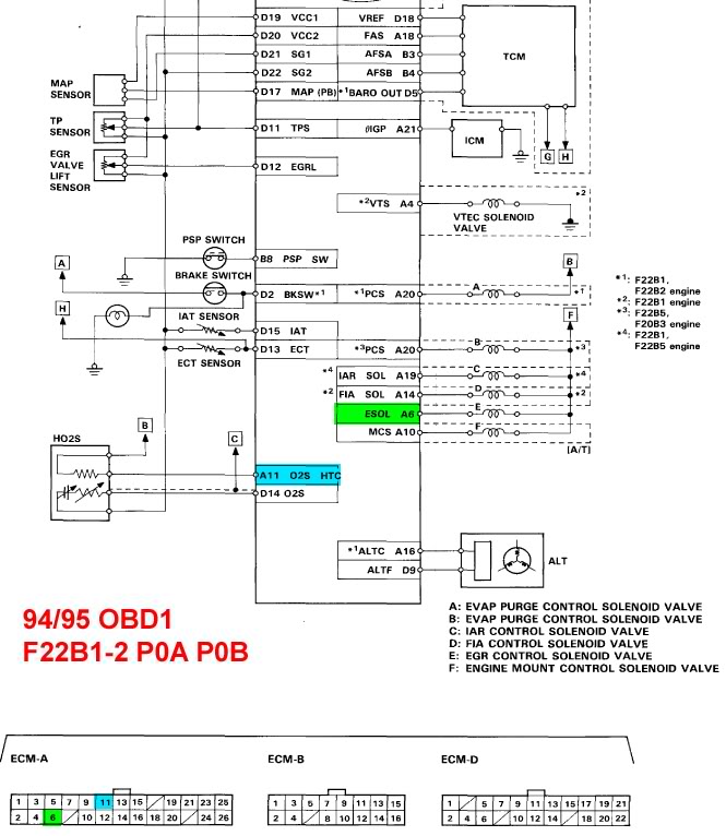
The O2 sensor has two circuits. The top one is the heater (voltage from B going to A11 on the picture above). All that does is heat the sensor, so the computer can read the signal faster. If voltage is missing at pin A11, then you get an error code for heater circuit malfunction.
The second circuit is the signal. There is a 5V reference voltage going to O2 sensor, Map, CYP, etc.. in the diagram above. Then the signal goes to D14. My guess for the dotted line and the connection to C (Ground) would mean this is a shielded wire?

Super Moderator
Joined: Oct 2010
Posts: 7,099
From: United States
As stated previously, the heated oxygen sensor (HO2S) input should be a Wht/Red wire to pin D14.
Another Wht/Red wire, which is at pin D9, is for the alternator FR signal.
Super Moderator
Joined: Oct 2010
Posts: 7,099
From: United States
I don't know what source this diagram you posted is from. However pin A11 is a red wire for EGR control solenoid valve control at ECM Connector A, not related to the heated oxygen sensor.
Super Moderator
Joined: Oct 2010
Posts: 7,099
From: United States
I will only temporarily posted these attached images, to allow you to see. However, after you've seen them, I will delete them.
Last edited by redbull-1; Jan 9, 2014 at 09:55 PM. Reason: Images removed.

Thread Starter
|
Member
Joined: Jan 2013
Posts: 185
From: Olympia, WA
I was looking for a P0A wiring diagram and that's the only one i could find. Either way, I found the O2 sensor signal, wired the circuit however I think I may have crossed a wire somewhere because it's measuring voltage from the battery/alternator instead of the o2. Granted, the O2 sensor only puts out about a volt at full rich, but still, something weird is going on. Looks cool, though! Hopefully I'll have it figured out relatively soon. Secondary question: by unplugging my ecu, did i just reset it?

Super Moderator
Joined: Oct 2010
Posts: 7,099
From: United States
I was looking for a P0A wiring diagram and that's the only one i could find. Either way, I found the O2 sensor signal, wired the circuit however I think I may have crossed a wire somewhere because it's measuring voltage from the battery/alternator instead of the o2. Granted, the O2 sensor only puts out about a volt at full rich, but still, something weird is going on. Looks cool, though! Hopefully I'll have it figured out relatively soon. Secondary question: by unplugging my ecu, did i just reset it?
If you disconnected the ECU, it will reset.

Been Around A Long Time Member
Joined: Jul 2011
Posts: 1,008
From: Denver
More ECU pinout diagrams: innovatemotorsports(dot)com/resources/ecu_pinout(dot)php

Junior Member
Joined: Nov 2013
Posts: 43
Also remember that the WHT/RED signal wire from the O2 sensor is shielded as indicated by the dotted line running along side of it in that ECU pin out diagram. D14 is on the bottom row of pins just to the right of the connector center, while D9 is on the top row and to the left.
Just to clarify something as well;
90-95 OBD1 ECU pins are numbered
1 3 5 7 etc etc
2 4 6 8 etc etc
96+ OBD2a and OBD2b ECUs are
1 2 3 4 etc etc
11 12 13 14 etc etc
Also they are portrayed as if looking at the back of the connector going into the ECU.
Last edited by CD5Accord; Jan 10, 2014 at 01:57 PM.

