
Need Wiring Diagram


Thread Starter
|
Been Around A Long Time Member
Joined: Sep 2010
Posts: 1,653
From: Tennessee
Hello
While pulling out my motor and trans I pulled too hard on this connector and pulled the wires out.
Can someone tell me where they go?
It is the connector right under the distributor.
There are 4 wires
Please and thank you
While pulling out my motor and trans I pulled too hard on this connector and pulled the wires out.
Can someone tell me where they go?
It is the connector right under the distributor.
There are 4 wires
Please and thank you
Thread Starter
|
Been Around A Long Time Member
Joined: Sep 2010
Posts: 1,653
From: Tennessee
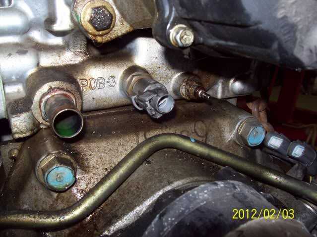
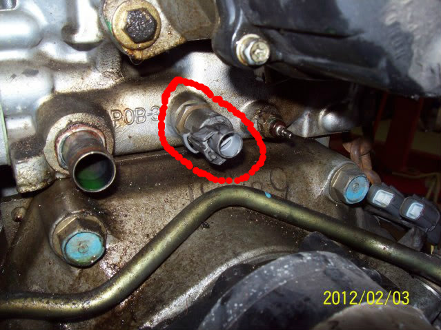
well those are the same colors except for the black wire however this looks like some kind of temp sensor.
Here I circled where the wires pulled out from.
again thanks for the help!!
Here I circled where the wires pulled out from.
again thanks for the help!!

Super Moderator
Joined: May 2010
Posts: 11,834
From: Kenton, TN
That is the ECT, only two wires to it? If they are the same on the 97 vs 95, majestic has the part number the same 37870-PK2-015 for a 95EX to a 97EX. Then there is a single black wire to the temp gauge sender.....just to the right in your pic.
I show the wires to the ECT as GRN/BLU and RED/WHT for a 95.
I show the wires to the ECT as GRN/BLU and RED/WHT for a 95.
Thread Starter
|
Been Around A Long Time Member
Joined: Sep 2010
Posts: 1,653
From: Tennessee
you are right, the black does go to the sensor next to it on the right.
I am going to pull the connector off and get a better look at it.
However those 3 wires go into the connector for sure.
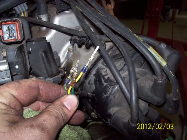
The wires are
Green
Yellow
Green with yellow dashes
I am going to pull the connector off and get a better look at it.
However those 3 wires go into the connector for sure.
The wires are
Green
Yellow
Green with yellow dashes

Thread Starter
|
Been Around A Long Time Member
Joined: Sep 2010
Posts: 1,653
From: Tennessee
OK - I looked more carefully.
You are right, those 4 wires are coming right out from the base of the distributor.
The other connector that I circled did in fact only have 2 wires going to it, I repined that connector with its 2 wires. I assumed that it did not matter which pin went in which hole as it is most likely just a temp sensor of some type.
Anyway as for the 4 wires coming out of the distributor I looked and looked and did not find a connector anywhere that was missing its wires.
The diagram you posted up is def the right one, those are the wires. The ICM is located in the Dist, right? I guess when I put the motor back in (Monday or Tuesday) I should find the connector they belong in. However, I will need to know what positions they have to go in unless the colors match on both sides of the connector (I hope they do)
So thank you Poorman for the help so far.
Super Moderator
Joined: May 2010
Posts: 11,834
From: Kenton, TN
On the ECT, I think it does matter....or at least I'd bet a cup of coffee on it. The ect is a "resister" of sorts. One wire is + the other is -.....again I'm not an electrical engineer, I'd have to call my Dad. These feed back to the ECU to tell it when the engine is warm/cold and it can adjust "things", if you will, the "choke" for a FI engine.
For the others, is there an 8 pin and 2 pin connector near by....is one or both of them missing a few wires? EDIT: or what plugs into the coil, if it is external....4 pin
For the others, is there an 8 pin and 2 pin connector near by....is one or both of them missing a few wires? EDIT: or what plugs into the coil, if it is external....4 pin
Last edited by poorman212; Feb 5, 2012 at 07:07 AM.
Thread Starter
|
Been Around A Long Time Member
Joined: Sep 2010
Posts: 1,653
From: Tennessee
On the ECT, I think it does matter....or at least I'd bet a cup of coffee on it. The ect is a "resister" of sorts. One wire is + the other is -.....again I'm not an electrical engineer, I'd have to call my Dad. These feed back to the ECU to tell it when the engine is warm/cold and it can adjust "things", if you will, the "choke" for a FI engine.
For the others, is there an 8 pin and 2 pin connector near by....is one or both of them missing a few wires? EDIT: or what plugs into the coil, if it is external....4 pin
For the others, is there an 8 pin and 2 pin connector near by....is one or both of them missing a few wires? EDIT: or what plugs into the coil, if it is external....4 pin
Thanks for pointing out that the 4 wires could have pulled out from a 8 pin connector.
I was looking for a 4 pin connector missing it's wires.
What you said was kinda obvious but it just didn't occur to me, so thank you very much for the help. I will check it out today and figure out where they went and hopefully you will be able to find the diagram that shows the positions they go in.
Thank you very much for your help!

Thread
Thread Starter
Forum
Replies
Last Post