
HELP! No Spark - Bad ECM???


#14
 11-02-2015, 02:38 PM
yes, 1995 accord 2.7L V6 -ignitor module in distributor and coil mounted below distributor to engine block.
I have a nice square wave on the green/yellow wire coming from ICM and then a different looking wave on the green wire between ICM and coil. it has some sharper points, not typical square wave at all but it does seem to be about the same frequency as the other wave.
thanks!
PS:
just to refresh: Car had been sitting for 2+ years;
Ran when I got it started;
then started missing on #3 and I found that the exhaust rockers had fallen off and were laying in under the valve cover (weird, right?);
Pulled cam and put it back together & it was running right again;
went to wal mart & go oil change & on my way home exhaust fell off and I wired it up on the side of the road;
Parked car and when I went out the next day it was barely running and now I just get like one spark, then nothing!
Seems like none of the above have anything to do with one another.
I had also thought that maybe I overtorqued the cam bolts but that was not the case.
thanks again!
#15
11-02-2015, 06:12 PM
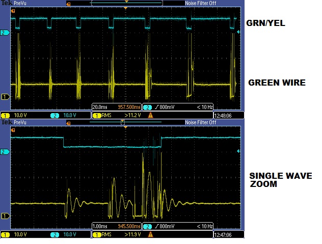
Here is a pic of the grn/yel wire (ICM to ECM) = top wave (blue trace)
and the green wire (ICM to COIL) = lower (yellow trace)
Engine cranking, no start.
Do these waves look like they should? I think the top (blue) wave is good but not sure about the green distributor wire wave (yellow wave).
The voltage is set for 10v per division in both screens.
Time= top screen 20mS/div; lower screen is 1mS per division.
pulse width is about 4.25mS
If you look closely you can see that the ICM/ECM (grn/yel) wire is not being pulled completely to ground, only down to about 4v. is that a problem that would cause the no start condition?
Again, this is a 1995 Accord 2.7L V6.
No stored codes.
Any suggestions where to go from here?
Thanks a LOT!
#16
11-02-2015, 10:59 PM

I may have made a mistake on the voltages to the yel/grn wire between the ICM and ECU. The shop manual I have says the voltage should be 12V when the key is in the II position and engine is not running. Then you will have pulses (square waves) when the engine is running.
The yel/grn wire is at A11 on the ECU. The A connector has 26 pins with one wire missing. The top row is numbered 1-13 and the bottom row is 14-26. You may want to repeat this test at the ECU on pin A11. Also try the quick voltage test.
Here is a site with some good information:
Igniter function
Igniter failures
#17
11-04-2015, 08:38 AM
Thanks for all the great info PAhonda!
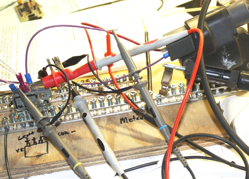
After I got an understanding of the ignition circuit I made a test jig to test the ignitor using a bench power supply and signal generator to simulate the ECM signal. The ICM tested good (all of them). Then I added the coil and a spark tester to the circuit and was able to simulate spark.
The only time that I was able to replicate anything like what was happening was when the current was turned down, causing a voltage drop.
I believe that my problem is in either the power supply wire or the coil ground (that is, unless the coil that is in the car is defective -but I believe it's OK since I tried a few different ones with the same results.
I'll post the results when I find the problem.
Thanks again for your help.
Here is a pic of my test jig. Not pretty but very effective!
#18
11-04-2015, 03:51 PM
Did you see this?
http://archivos.diagramas.mx/automov...ng_diagram.pdf
I understand its for a 97, but I looked and the set up is the same.
http://archivos.diagramas.mx/automov...ng_diagram.pdf
I understand its for a 97, but I looked and the set up is the same.
#20
11-08-2015, 03:51 AM
The grounding of the ECM seems to be solid, and so does the engine grounding.
I suspect now that the transistor that controls ignition is failing because it is not pulling the signal all the way to ground (the square wave only goes down to like 3.9v rather than zero). When I bench tested the ICM & coil I used a signal generator to simulate the ECM signal but I am going to test the ECM on the bench and see what I can find out. There is one identical transistor on the ECM board that I can compare to and maybe even steal if I need to replace Q40 (IGN output). >> I would just replace it with a compatible transistor but it is an uncommon part that, unlike a standard transistor that uses a bias resistor at the base input, this one (and most of the other transistors in the ECM) contains the bias resistor and other components in the package so that it is the ONLY device between the microprocessor and the ICM. Pretty cool design really, makes it simple to manufacture and troubleshoot but the highly specialized parts are not things you can go to a local parts distributor and buy.
I'll attach a schematic later for anybody who is interested.
One last thing: does anybody know where schematics for Honda ECM's can be located?
Thank you for all your help! dw