
HELP! No Spark - Bad ECM???
#21
 11-08-2015, 06:41 AM


[QUOTE=PAhonda;364392]
The yel/grn wire is at A11 on the ECU. The A connector has 26 pins with one wire missing. The top row is numbered 1-13 and the bottom row is 14-26. You may want to repeat this test at the ECU on pin A11. Also try the quick voltage test.
PAhonda,
Thank you again for the great info.
I have a question about the pin numbers on the ECM:
Most of the pinouts I have seen for the OBD1 accords have the pins listed as:
Top row= 1, 3, 5, 7...
Bottom row= 2, 4, 6, 8...
This 95 Odyssey pinout lists the IGN pin as pin 21, although it is in the same position as pin A11 would be if counting 1, 2, 3, 4, 5.... across
ECU wiring diagram?
Pin A11 per your instruction was in the right place
But this is confusing that there are conflicting pinouts. Then, to top it all off, the numbers on the actual circuit board start at #1, starting at the top/right position (pin 13).
SO there are three different pinouts for the same ECM!
My main concern is this: I want to steal the transistor from D4 (K-Link) to replace the defective transistor @ A11 (IGN). Just need to make sure I am not stealing a transistor that is going to cause the car not to run!
K-link is just for diagnosis, right?
And it is D4 (forth pin from top left on the right end terminal of the ECM), right?
I think this solve my ignition problem because the transistor (actually an IC that looks like a transistor) tested defective on the bench.
Thnaks!
#22
11-08-2015, 11:52 PM

I was using the pinout from a shop manual I bought on CD many years ago that has information on the 4 cylinder and V6 engine. I am using my work computer, so I don't have access to the pdfs.
I'd probably suggest picking up a used PCM/ECU from a junkyard to use as the source.
I'd probably suggest picking up a used PCM/ECU from a junkyard to use as the source.
#23
11-09-2015, 01:39 AM
It was a bad Q40 in the ECM that totally disabled engine.
As soon as I installed the ECM I saw good spark, installed distributor cap & wires & it started up after a bit of cranking (due to all the unburnt fuel in the cylinders), smoked for a while and is running strong now.
Should have bought a used ECM but I had thrown so many parts at the thing and was seeing a square wave at the ECM (just not strong enough to pull all the way to ground). Live and learn!
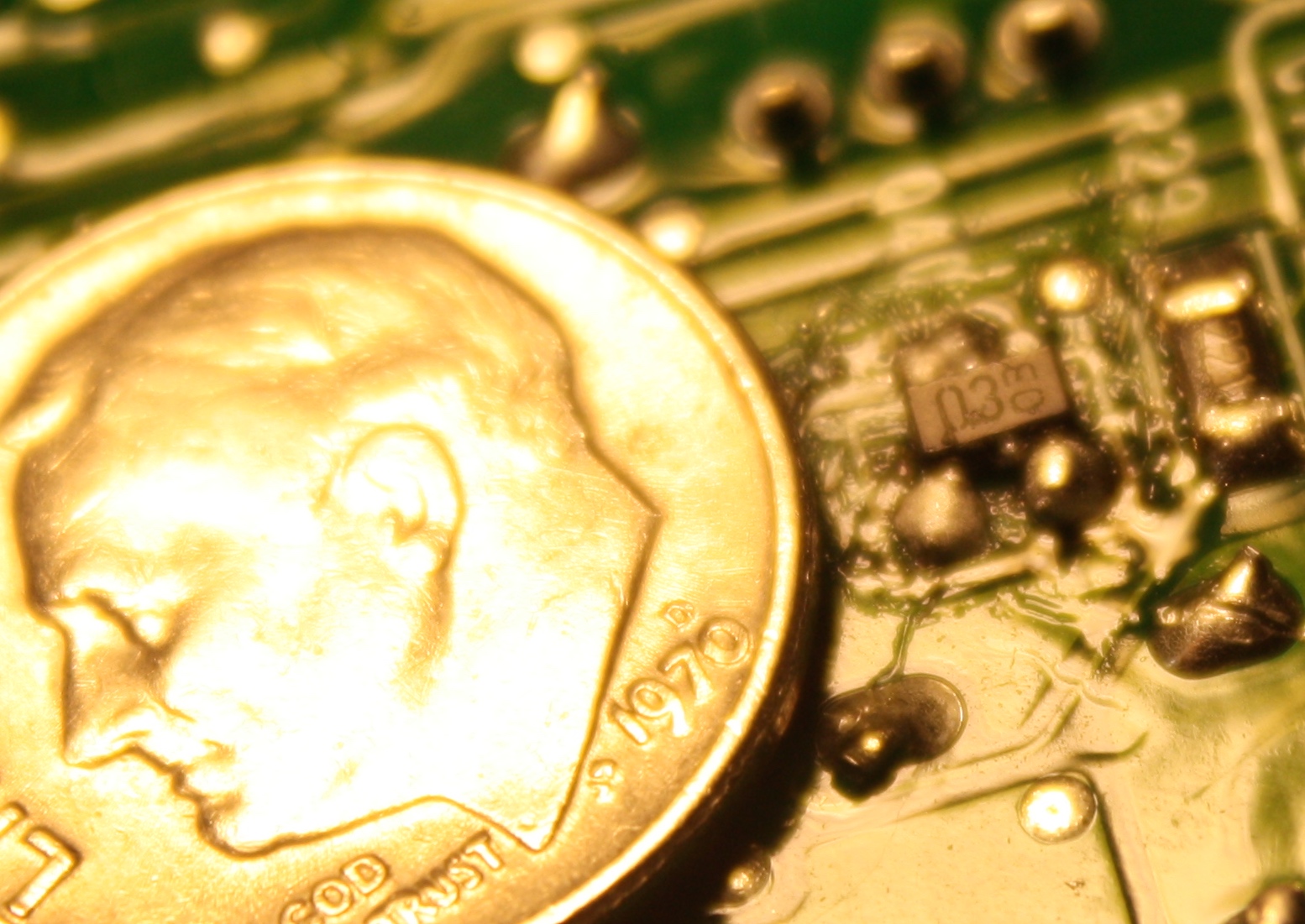
I should add that removing and replacing these surface mount transistors is not quite as easy as a through-hole type component. You can easily damage the circuit board with too much heat. I used this alloy material called "Chip Quick" that looks like regular solder but has a much lower melting point. As it mixes with the original solder it makes it much easier to melt all of the joints at once and remove the component -Makes easy work out of the job.
THis was the first time I had opened an ECM -all of the mystery went away as it's just another microcontroller with a bunch of inputs and outputs...
The culprit:
Almost done smoking

As soon as I installed the ECM I saw good spark, installed distributor cap & wires & it started up after a bit of cranking (due to all the unburnt fuel in the cylinders), smoked for a while and is running strong now.
Should have bought a used ECM but I had thrown so many parts at the thing and was seeing a square wave at the ECM (just not strong enough to pull all the way to ground). Live and learn!
I should add that removing and replacing these surface mount transistors is not quite as easy as a through-hole type component. You can easily damage the circuit board with too much heat. I used this alloy material called "Chip Quick" that looks like regular solder but has a much lower melting point. As it mixes with the original solder it makes it much easier to melt all of the joints at once and remove the component -Makes easy work out of the job.
THis was the first time I had opened an ECM -all of the mystery went away as it's just another microcontroller with a bunch of inputs and outputs...
The culprit:
Almost done smoking

Thread
Thread Starter
Forum
Replies
Last Post