
99 Accord DX 2.3L - Head Gasket Endeavor


Super Moderator : And A Texan
Joined: Feb 2007
Posts: 9,652
From: Katy, TX
Examine PCV system from valve cover to throttle body for leaks, cracks, disconnected.
Examine brake booster line from throttle body to brake booster for leaks, cracks, disconnected.
Check EVAP system for vacuum leaks tracing from intake manifold.
Listen for hissing sound of vacuum leak.
Try disconnecting IACV electrical connector to see if idle stablizes. Idle may still be high, but this would confirm air leaking into system somewhere.
Other possibilities are intake manifold leak, valve cover leak.
Shop manual says for idle fluction to perform idle speed adjustment, inspect/adjust throttle cable, inspect/test throttle body. You need the shop manual to address these.
good luck
Super Moderator : And A Texan
Joined: Feb 2007
Posts: 9,652
From: Katy, TX
This is PCV air intake. It should be sealed to insure cleaned air enters crankcase.
I doubt this is your problem since air is getting in, although unfiltered, which is what was supposed to happen anyway.
Did you find PCV hose from valve cover to throttle body? I've left this off accidentally on my 94 EX and got the cyclic idle speed problem.
good luck
I doubt this is your problem since air is getting in, although unfiltered, which is what was supposed to happen anyway.
Did you find PCV hose from valve cover to throttle body? I've left this off accidentally on my 94 EX and got the cyclic idle speed problem.
good luck

Thread Starter
|
Junior Member
Joined: Sep 2013
Posts: 53
Warning, a little long.
I decided after reviewing the shop manual that I would revisit the alignment of all the components in the timing/balance loop. I discovered the front balance shaft sprocket was off slightly and the rear one I'm not so sure. I also realized that what I thought was TDC on the Camshaft (UP arrow matching square on head isn't exactly 100%) wasn't so my valve adjustment could be off slightly. I can recheck those easy enough, so on to my questions.
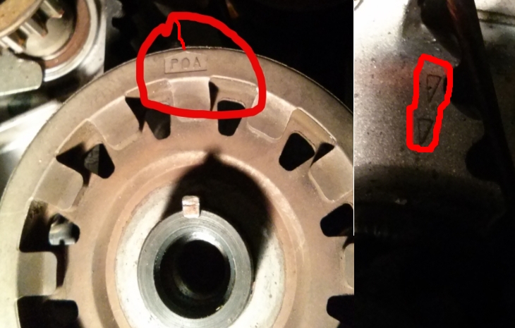
The first picture has front and rear balance shaft sprockets and crack sprocket. My first question is about the balance shaft sprockets. I know how to align the one on the left. But the one on the right has a notch in the face of one of the belt guide rises (in Red). What am I supposed to align that with? I see several circle shaped "rises" (like the ones in blue) on the block around the circumference of the space but that's it. No arrow or corresponding "notch". Does it matter for this sprocket? I know for the water pump it doesn't matter. My last question for this picture is the white paint marks noted in green on crankshaft sprocket and balance sprocket? Are these something someone put here or were they there from the factory? What purpose do they serve?

In the below image, on the left (on crank sprocket), is the tip of the "arrow" supposed to match up with the arrow on the block on the right side of the image? As that where crankshaft is at TDC?
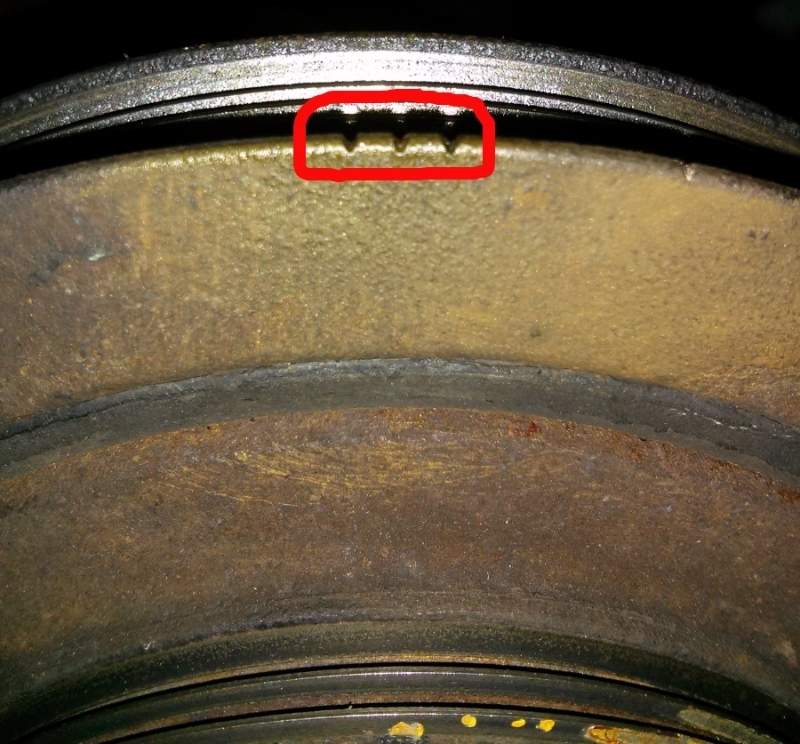
And Lastly, are the marks below on the crankshaft pulley the ones that are supposed to line up with the pointer on the lower timing cover?
Thanks for your help.
I decided after reviewing the shop manual that I would revisit the alignment of all the components in the timing/balance loop. I discovered the front balance shaft sprocket was off slightly and the rear one I'm not so sure. I also realized that what I thought was TDC on the Camshaft (UP arrow matching square on head isn't exactly 100%) wasn't so my valve adjustment could be off slightly. I can recheck those easy enough, so on to my questions.
The first picture has front and rear balance shaft sprockets and crack sprocket. My first question is about the balance shaft sprockets. I know how to align the one on the left. But the one on the right has a notch in the face of one of the belt guide rises (in Red). What am I supposed to align that with? I see several circle shaped "rises" (like the ones in blue) on the block around the circumference of the space but that's it. No arrow or corresponding "notch". Does it matter for this sprocket? I know for the water pump it doesn't matter. My last question for this picture is the white paint marks noted in green on crankshaft sprocket and balance sprocket? Are these something someone put here or were they there from the factory? What purpose do they serve?

In the below image, on the left (on crank sprocket), is the tip of the "arrow" supposed to match up with the arrow on the block on the right side of the image? As that where crankshaft is at TDC?

And Lastly, are the marks below on the crankshaft pulley the ones that are supposed to line up with the pointer on the lower timing cover?

Thanks for your help.
Super Moderator
Joined: May 2006
Posts: 18,398
From: Wisconsin
I don't know what the white paint is; my 1998 didn't have that.
For the rear balance-shaft sprocket, there's a gearset behind that pulley, so those marks should be ignored. There's a plug in the back side of the head where you insert a pin (allen wrench or drill bit or something). That locks the actual shaft in the proper position.
The "P0A" on the crankshaft sprocket is a fragment of a part number, not an arrow. There was some kind of mark in that pulley to line up with an arrow on the oilpump casting. I don't remember exactly where that was but maybe around 2-oclock position???
The 3 notches in your last picture are for spark timing (15deg BTDC +/-2) so they are not to be used for camshaft timing. The actual TDC mark (single notch) is visible over to the right at about 1-oclock. That lines up with the arrow in the plastic lower timing cover.
Not shown, but you mention the arrow on the camshaft sprocket. The REAL timing marks are 2 notches out at the teeth of the sprocket. Those line up with the top of the head (or top of the sheetmetal cover behind the sprocket). The arrow only indicates whether it's at TDC compression stroke (up) vs. TDC exhaust stroke (pointing down).
Thread Starter
|
Junior Member
Joined: Sep 2013
Posts: 53
Not shown, but you mention the arrow on the camshaft sprocket. The REAL timing marks are 2 notches out at the teeth of the sprocket. Those line up with the top of the head (or top of the sheetmetal cover behind the sprocket). The arrow only indicates whether it's at TDC compression stroke (up) vs. TDC exhaust stroke (pointing down).
Super Moderator
Joined: May 2006
Posts: 18,398
From: Wisconsin
Top picture... what's visible is the large balance-belt sprocket on the crankshaft. Pull that off & look at the smaller cam-belt sprocket. THAT one should have a dimple in the face, out at the teeth. Arrow cast into the front of the engine (oilpump) is probably obstructed by the balance-belt sprocket.
Thread Starter
|
Junior Member
Joined: Sep 2013
Posts: 53
I don't know what the white paint is; my 1998 didn't have that.
For the rear balance-shaft sprocket, there's a gearset behind that pulley, so those marks should be ignored. There's a plug in the back side of the head where you insert a pin (allen wrench or drill bit or something). That locks the actual shaft in the proper position.
The "P0A" on the crankshaft sprocket is a fragment of a part number, not an arrow. There was some kind of mark in that pulley to line up with an arrow on the oilpump casting. I don't remember exactly where that was but maybe around 2-oclock position???
The 3 notches in your last picture are for spark timing (15deg BTDC +/-2) so they are not to be used for camshaft timing. The actual TDC mark (single notch) is visible over to the right at about 1-oclock. That lines up with the arrow in the plastic lower timing cover.
Not shown, but you mention the arrow on the camshaft sprocket. The REAL timing marks are 2 notches out at the teeth of the sprocket. Those line up with the top of the head (or top of the sheetmetal cover behind the sprocket). The arrow only indicates whether it's at TDC compression stroke (up) vs. TDC exhaust stroke (pointing down).
For the rear balance-shaft sprocket, there's a gearset behind that pulley, so those marks should be ignored. There's a plug in the back side of the head where you insert a pin (allen wrench or drill bit or something). That locks the actual shaft in the proper position.
The "P0A" on the crankshaft sprocket is a fragment of a part number, not an arrow. There was some kind of mark in that pulley to line up with an arrow on the oilpump casting. I don't remember exactly where that was but maybe around 2-oclock position???
The 3 notches in your last picture are for spark timing (15deg BTDC +/-2) so they are not to be used for camshaft timing. The actual TDC mark (single notch) is visible over to the right at about 1-oclock. That lines up with the arrow in the plastic lower timing cover.
Not shown, but you mention the arrow on the camshaft sprocket. The REAL timing marks are 2 notches out at the teeth of the sprocket. Those line up with the top of the head (or top of the sheetmetal cover behind the sprocket). The arrow only indicates whether it's at TDC compression stroke (up) vs. TDC exhaust stroke (pointing down).
Top picture... what's visible is the large balance-belt sprocket on the crankshaft. Pull that off & look at the smaller cam-belt sprocket. THAT one should have a dimple in the face, out at the teeth. Arrow cast into the front of the engine (oilpump) is probably obstructed by the balance-belt sprocket.
Thread Starter
|
Junior Member
Joined: Sep 2013
Posts: 53
Thanks to your help again, everything lined up and timing/balance belt back on. If I ever need to do this gain I could easily do it in a weekend instead of 2 months. Ignorance has definitely been my enemy.
But, we still have the rough start, high (2200RPM) and pulsing idle(1200-2200RPM) after reaching temp. No check engine line, and my diagnostic tool shows no problem/errors. Coolant is topped off. But I just thought of something else, not sure if this would cause what I'm experiencing. When I took the distributor off, I didn't mark anything, and there were no obvious where marks to show the previous position. Could ignition timing be off causing this problem?
But, we still have the rough start, high (2200RPM) and pulsing idle(1200-2200RPM) after reaching temp. No check engine line, and my diagnostic tool shows no problem/errors. Coolant is topped off. But I just thought of something else, not sure if this would cause what I'm experiencing. When I took the distributor off, I didn't mark anything, and there were no obvious where marks to show the previous position. Could ignition timing be off causing this problem?
Super Moderator
Joined: May 2006
Posts: 18,398
From: Wisconsin
Not from the distributor position.
In 1998/1999 the spark timing is based on signals from a sensor down at the crankshaft. You can check it with a timing light, but you can't do anything about it.
Post #44, top photo, there's wires visible coming from sensors that are obstructed by the big crankshaft sprocket. Any adjustment of timing would come from the mounting bolts of those sensors - which aren't supposed to have any real slop for movement in the mounting-bolt-holes.
The timing sensor in the distributor is only there to differentiate between TDC of the compression stroke vs. TDC exhaust stroke. If you were to enlarge the distributor mounting holes into slots (like an older distributor), you could spin the distributor and the spark timing would not change.